Fuel assembly positioning grid capable of preventing fuel rod from being scratched and subjected to vibrating abrasion

A technology for positioning grids and fuel assemblies, which is applied in the assembly of fuel elements, greenhouse gas reduction, nuclear power generation, etc. It can solve the problems of large shading area, fuel rod abrasion, and large grid pressure drop, etc., to reduce the shading area, Reduce vibration and abrasion, reduce the effect of pressure drop

Active Publication Date: 2013-06-26
SHANGHAI NUCLEAR ENG RES & DESIGN INST CO LTD
View PDF5 Cites 20 Cited by
  • Summary
  • Abstract
  • Description
  • Claims
  • Application Information

AI Technical Summary

Problems solved by technology

However, due to the longitudinal arrangement of the springs, the shielding area in the flow direction is relatively large, which will lead to a large overall pressure drop of the grid
At the same time, its three-bend structure leads to point contact between the fuel rod and the grid spring, the contact area is small, and the surface of the fuel rod is more likely to be eroded due to flow-induced vibration

Method used


Image

  • Fuel assembly positioning grid capable of preventing fuel rod from being scratched and subjected to vibrating abrasion
  • Fuel assembly positioning grid capable of preventing fuel rod from being scratched and subjected to vibrating abrasion
  • Fuel assembly positioning grid capable of preventing fuel rod from being scratched and subjected to vibrating abrasion

Examples


Embodiment 1

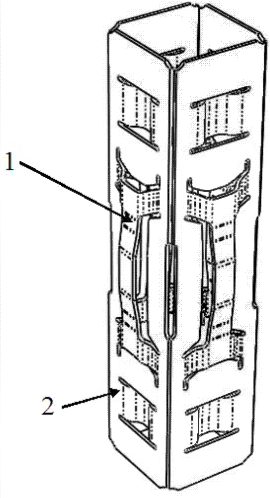
[0024] Such as figure 1 As shown, the fuel assembly positioning grid of the present invention is a square grid, and two upper and lower rigid protrusions 2 are arranged on the side wall of each cell, and a positioning grid is arranged between the two rigid protrusions 2 spring 1.

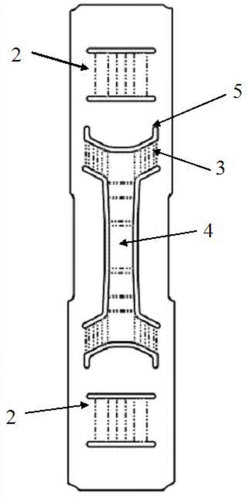
[0025] Such as Figure 2 to Figure 5 As shown, the positioning grid spring 1 is in the shape of an "I" as a whole, including two arched first-stage springs 3 arranged up and down, and a strip-shaped second-stage spring 4 .

[0026] The two first-stage springs 3 are arranged laterally. In order to balance the stiffness of the two-stage springs, the first-stage spring 3 extends obliquely toward the middle to increase the span of the spring. The turning point of the first-stage spring 3 is smoothly transitioned, and at the same time, there is a stress relief groove 5 with a width of about 0.5mm around the first-stage spring 3. The stress relief groove 5 mainly has two functions: one is to punch the ...

Embodiment 2

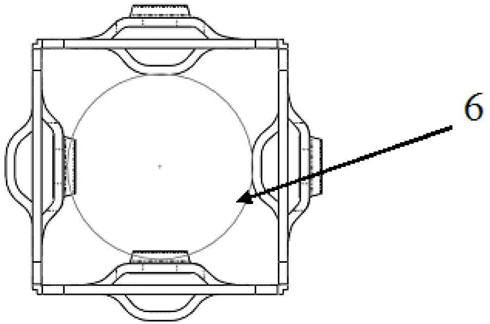
[0030] Such as Image 6 As shown, it differs from Embodiment 1 in that: the first-stage spring (3) does not have an inclined structure towards the middle; the top plane width of the second-stage spring 4 increases.


PUM


Abstract

The invention provides a fuel assembly positioning grid capable of preventing a fuel rod from being scratched and subjected to vibrating abrasion. An upper rigid dimple and a lower rigid dimple are uniformly distributed on the side wall of each grid cell; a positioning grid spring is arranged between every two rigid dimples; the whole body of each positioning grid spring is of an I-type and each positioning grid spring comprises two arched primary springs which are arranged at the upper part and the lower part, as well as a strip-shaped secondary spring; the two primary springs are arranged transversely; the height of each primary spring is smaller than the spacing between a cladding surface and the side wall of the positioning grid when the fuel rod is located in the center of the positioning grid; the secondary spring is arranged longitudinally; and the two ends of the secondary spring are respectively connected to the centers of the primary springs and are slowly raised up to form two slopes, and the middle of the secondary spring is a top plane which is in direct contact with the surface of the fuel rod. The structure of the fuel assembly positioning grid is capable of effectively preventing the surface of the fuel rod from being scratched by the springs of the positioning grid and reducing the vibrating abrasion of the spring to the fuel rod, thereby improving the whole safety of a fuel assembly.

Description

technical field [0001] The invention relates to the technical field of fuel assemblies, in particular to a fuel assembly positioning grid capable of preventing fuel rods from scratching and vibration abrasion. Background technique [0002] The fuel assembly is a critical component of the nuclear reactor core that generates heat and transfers this heat energy to the coolant. The performance of the fuel assembly directly affects the safety and economics of the reactor. [0003] A fuel assembly is formed by a certain number of fuel rods arranged in a certain way in the fuel assembly skeleton. There are several positioning grids arranged at intervals along the axial direction on each fuel assembly skeleton. The positioning grid is a square grid structure composed of metal strips welded to each other. It uses the rigid support in each grid and six contacts composed of springs to clamp the fuel rods and position the fuel rods. [0004] The thermal energy of the fuel assembly is...

Claims


Application Information

Patent Timeline
Patent Type & Authority Applications(China)
IPC IPC(8): G21C3/34
CPCY02E30/30
Inventor 郑轶雄刘松刘家正丁捷李继威干富军
Owner SHANGHAI NUCLEAR ENG RES & DESIGN INST CO LTD
Why Eureka
Try Eureka