
Method for controlling reverse penetration into back of aluminium alloy pipeline during welding

A technology for aluminum alloy pipes and pipelines, applied in welding equipment, manufacturing tools, arc welding equipment, etc., can solve the problems of poor welding seam back forming, difficulty in using rigid mandrels for continuous bends, and increase production costs. The amount of reverse penetration on the back of the weld, good welding seam forming quality, and the effect of being beneficial to the welding seam forming

Active Publication Date: 2013-07-03
BEIJING HANGXING MACHINERY MFG CO LTD
View PDF5 Cites 9 Cited by
  • Summary
  • Abstract
  • Description
  • Claims
  • Application Information

AI Technical Summary

Problems solved by technology

In actual production, the method of imposing a rigid mandrel inside is often used to avoid this defect, but this method will be limited by the complexity of the pipeline on the one hand, and it is difficult to use a rigid mandrel for the butt joint of continuous elbows; on the other hand, welding is different. Pipelines with different diameters need to be matched with rigid mandrels of different diameters, which increases production costs
Therefore, the method of using a rigid mandrel cannot fully meet the welding requirements of today's complex aluminum alloy pipelines, and it will increase production costs and cannot guarantee the welding quality of pipelines.
[0004] As the structure and shape of aluminum alloy products become more and more complex, the shape of the internal pipeline of the product is also more and more complicated, and the control of the internal flow of the pipeline is becoming more and more strict. The amount of reverse transmission is too large, it is difficult to meet the requirements of the through-ball test, etc.
The method of using a rigid mandrel cannot completely control the back reflection and ensure the quality of pipeline welding, which limits the application of welding production of aluminum alloy complex pipeline structure products

Method used


Image

  • Method for controlling reverse penetration into back of aluminium alloy pipeline during welding
  • Method for controlling reverse penetration into back of aluminium alloy pipeline during welding
  • Method for controlling reverse penetration into back of aluminium alloy pipeline during welding

Examples


Embodiment 1

[0029] Example 1: Butt argon arc welding of 5A06 aluminum alloy pipeline

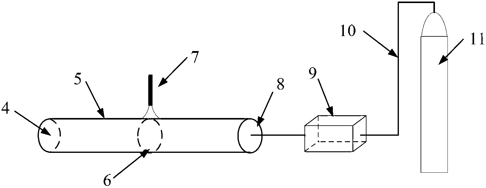
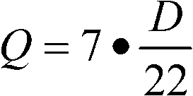
[0030] Base material: 5A06 aluminum alloy pipe with outer diameter of 38mm and wall thickness of 1.5mm, butt argon arc welding. The whole welding process is divided into two stages: the point-fixed air-filling stage and the welding pressure-regulating stage. After the pipeline is properly assembled and tapped, both ends of the pipeline are blocked. Start to fill the pipeline with argon at a flow rate of 12L / min. After inflating for 1-2 minutes, the welding will be carried out. The welding current is 50A. Gradually reduce the inflation flow to ensure the dynamic stability of the internal air pressure. The finally obtained pipeline welds are uniform and beautiful, without defects such as incomplete penetration and lack of fusion, and the back of the weld has a proper amount of reflection, which can meet the requirements of QJ919A-1998 for Φ32mm steel balls.

Embodiment 2

[0031] Example 2: Butt argon arc welding of 5A03 aluminum alloy pipeline

[0032] Base material: 5A03 aluminum alloy pipe with outer diameter of 22mm and wall thickness of 1.0mm, butt argon arc welding. The whole welding process is divided into two stages: the point-fixed air-filling stage and the welding pressure-regulating stage. After the pipeline is properly assembled and tapped, both ends of the pipeline are blocked. Start to fill the pipeline with argon. The flow of argon is 7L / min. After inflating for 1-2 minutes, the welding is carried out. The welding current is 40A. Gradually reduce the inflation flow to ensure the dynamic stability of the internal air pressure. The finally obtained pipeline welds are uniform and beautiful, without defects such as incomplete penetration or lack of fusion, and the back of the weld has a proper amount of reflection, which can meet the requirements of QJ919A-1998 for Φ17mm steel balls.

Embodiment 3

[0033] Example 3: Butt argon arc welding of 5A02 aluminum alloy pipeline

[0034] Base material: 5A02 aluminum alloy pipe with outer diameter of 40mm and wall thickness of 3.0mm, butt argon arc welding. The whole welding process is divided into two stages: the point-fixed air-filling stage and the welding pressure-regulating stage. After the pipeline is properly assembled and tapped, both ends of the pipeline are blocked. Start to fill the pipeline with argon. The flow of argon is 12.7L / min. After inflating for 1-2 minutes, the welding current is 55A. Gradually reduce the inflation flow to ensure the dynamic stability of the internal air pressure. The finally obtained pipeline weld is uniform and beautiful, without defects such as incomplete penetration and lack of fusion, and the amount of back reflection of the weld is appropriate, which can meet the requirements of QJ919A-1998 for Φ30mm steel balls.


PUM

PropertyMeasurementUnit
Outer diameteraaaaaaaaaa
Wall thicknessaaaaaaaaaa
Outer diameteraaaaaaaaaa

Abstract

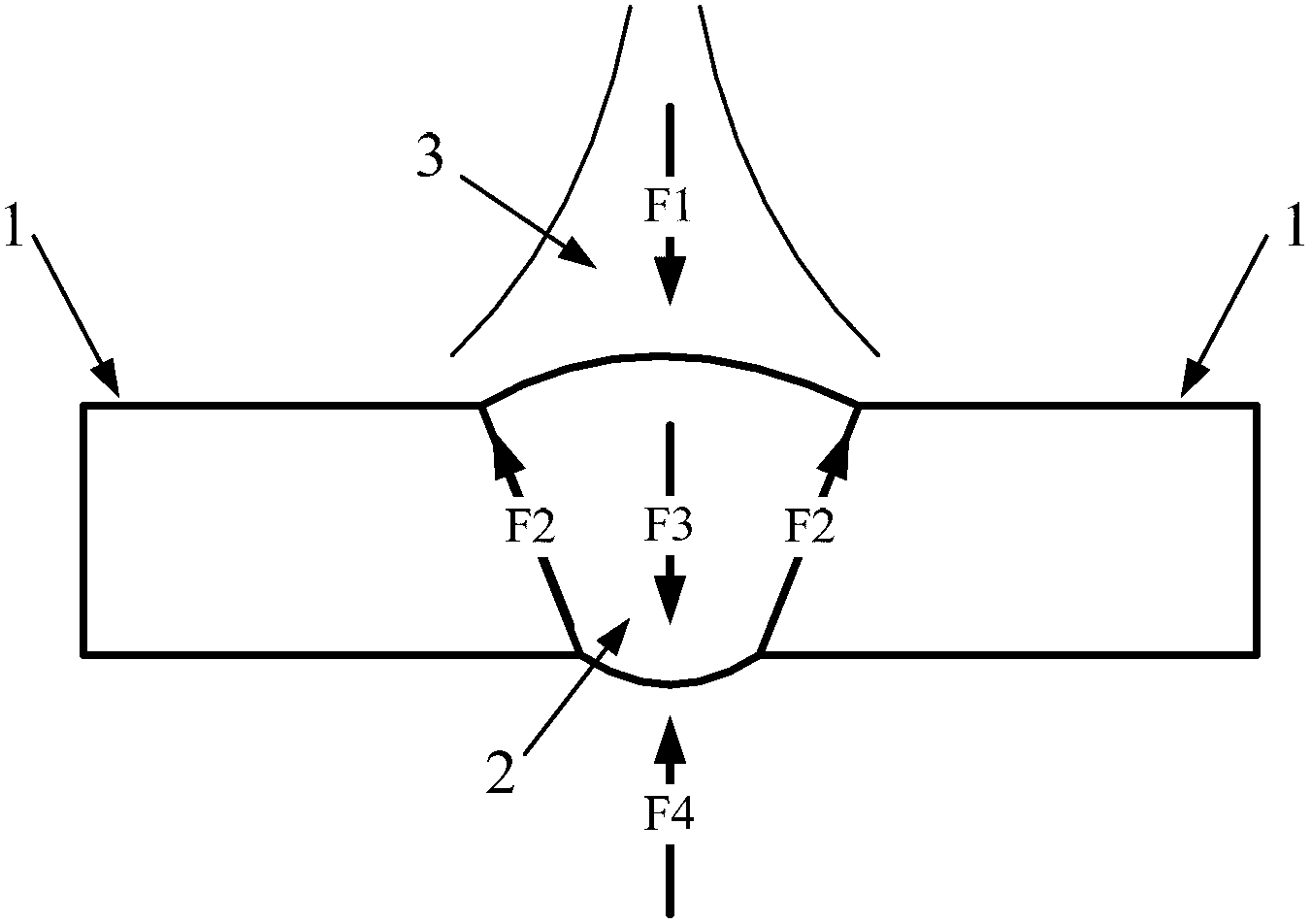
The invention provides a method for controlling reverse penetration into the back of an aluminium alloy pipeline during welding. In the method, inert gas is continuously inflated into a pipeline to be welded by using an adjustable pressure control device to ensure that the inflating flow is mutually coordinated with the deflating flow of an unwelded connector, so that the pressure in the pipeline reaches a macroscopic quasi-steady state, a steady and outward force is applied to a weld pool to prevent the back of the weld pool from collapsing to cause deformation, and thus the reverse penetration into the back of a weld joint can be effectively controlled. The method is not limited by complexity of the shape of the pipeline; the inert gas in the pipeline can play a role of a protective gas, so that the weld joint can be formed easily and the welding quality is ensured; therefore, by the method, the thin-wall, complex and multi-elbow pipeline with the wall thickness of 1.0-3.0mm and the external diameter of 22-40mm can be welded.

Description

Technical field [0001] The invention belongs to the technical field of welding, and relates to an aluminum alloy welding method, and more specifically to a method for controlling the back reflection of aluminum alloy pipeline welding, and can also be applied to other similar welding related fields. Background technique [0002] The aluminum alloy welded structure has excellent comprehensive properties such as light weight, good corrosion resistance, and easy processing. It is widely used in products in the fields of aerospace, defense and military industry. With the continuous development of model products, the requirements for aluminum alloy welding structure are becoming stricter, especially for the internal oil and gas pipelines of the product. Not only must the working pressure be considered, but also the back reflection of the weld must be controlled to ensure that the oil and gas flow in the pipe meets Design requirements, so the welding process of aluminum alloy pipelines ...

Claims


Application Information

Patent Timeline
IPC IPC(8): B23K9/16
Inventor 步贤政汪永阳李宏伟刘洋王志敏姚为
Owner BEIJING HANGXING MACHINERY MFG CO LTD
Learn More