Eureka AIR delivers breakthrough ideas for toughest innovation challenges, trusted by R&D personnel around the world.

Marking machine and automatic marking system

A technology of marking machine and frame, applied in the field of marking machine and automatic marking system, can solve the problems of operator's health injury, reduced production efficiency, inclined marking characters, etc., so as to improve production efficiency and avoid job change. cost, the effect of reducing quality problems

Active Publication Date: 2013-07-03
SHENNAN CIRCUITS
View PDF6 Cites 4 Cited by
  • Summary
  • Abstract
  • Description
  • Claims
  • Application Information

AI Technical Summary

Problems solved by technology

Due to the large noise and metal dust particles in the marking process, it will cause harm to the health of the operators; the marking process is generally separated from other processes, which increases the cost of job transfer and reduces production efficiency. In the process of manual marking, the shaking of hands may cause the marking characters to tilt, etc.

Method used


Image

  • Marking machine and automatic marking system
  • Marking machine and automatic marking system
  • Marking machine and automatic marking system

Examples


Embodiment 1

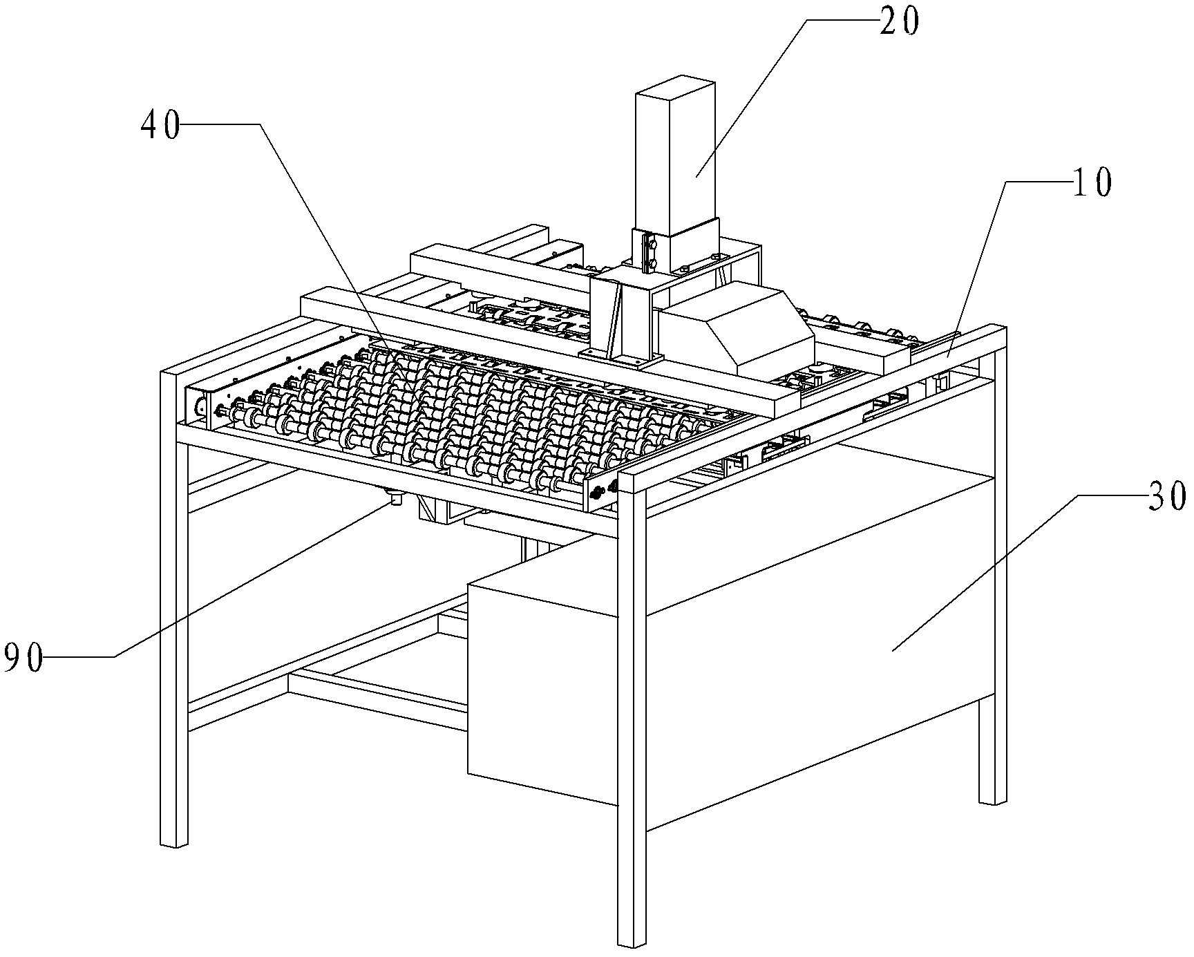
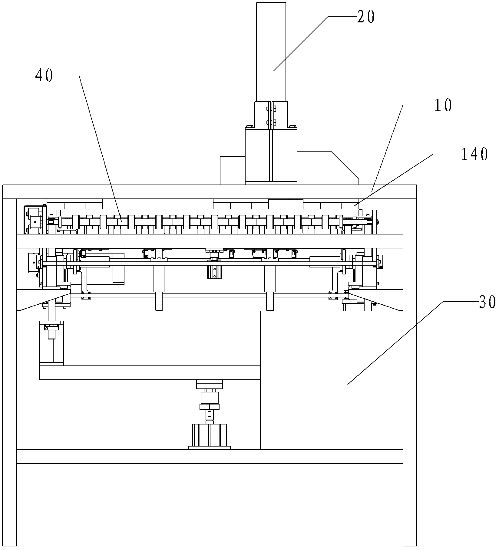
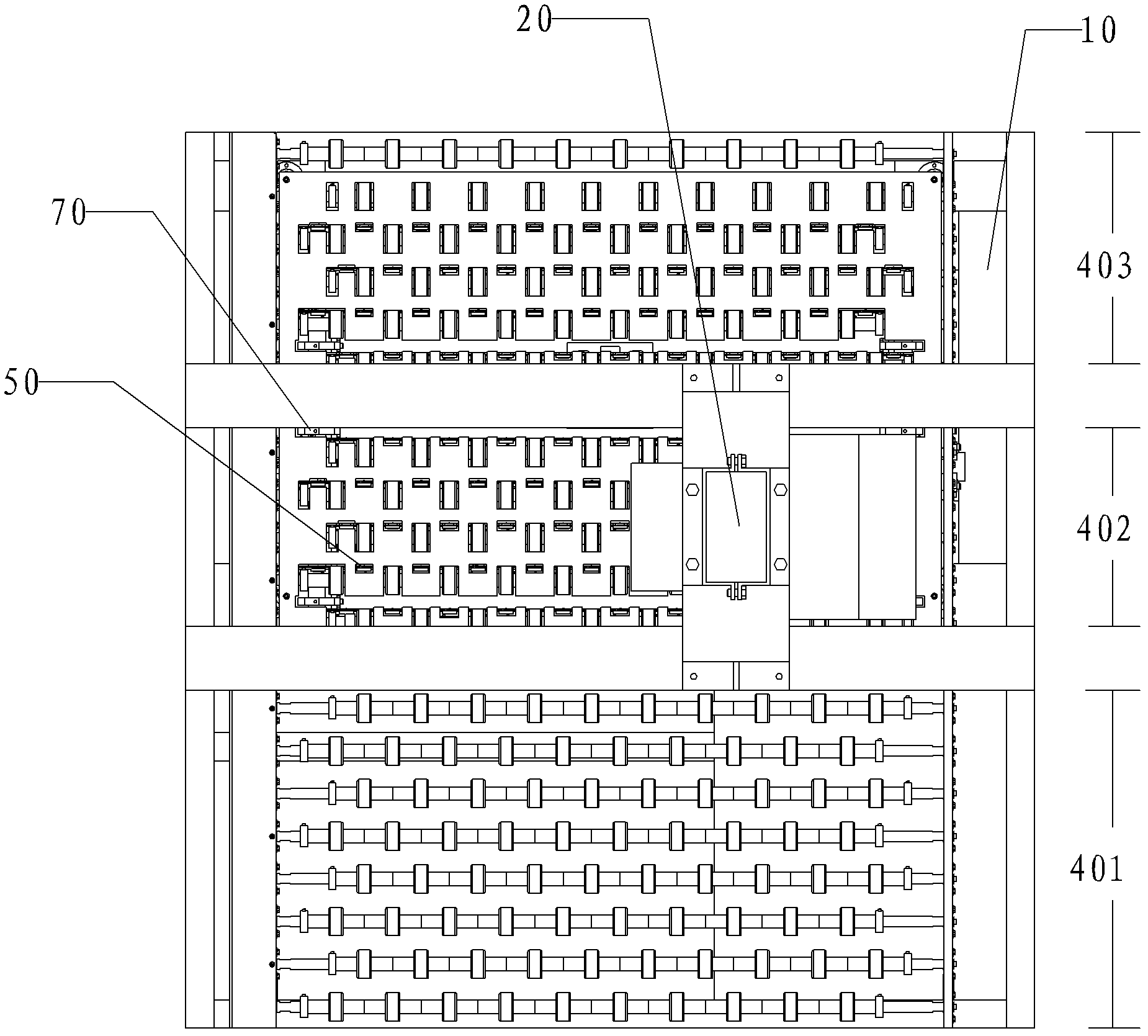
[0033] Reference Figure 1 to Figure 5 As shown, the marking machine of the present invention includes a frame 10 and a marking device 20 installed on the frame 10, an electrical control device 30, a transmission device, an adjustment device, a sensing device and a pressing device.

[0034] The marking device 20 includes a driving mechanism and a drill bit 203. The driving mechanism includes a control device 201 and a lifting cylinder 202. The control device 201 is electrically connected to the lifting cylinder 202, the computer 204, and the electrical control device 30, respectively. The piston rod of the lifting cylinder 202 is connected with the drill bit 203.

[0035] Reference image 3 As shown, the conveying device includes a driving motor and a conveying race 40, and the driving motor controls the operation of the conveying race 40. The conveying race 40 includes a feeding area 401, a working area 402, and an output area along the conveying direction. Material area 403, the...

Embodiment 2

[0054] Reference Image 6 As shown, the automatic marking system of the present invention includes an upstream assembly line 1000, a marking machine, and a downstream assembly line 3000. The marking machine is the marking machine in the above-mentioned embodiment, and the conveyor roller 40 of the marking machine The feed zone 401 is connected to the output end of the upstream assembly line 1000, and the discharge zone 403 of the conveying roller 40 of the marking machine is connected to the input end of the downstream assembly line 3000.

[0055] Using the automatic marking system of the present invention can realize automatic marking production without causing harm to the health of the operators, improving the working environment of the employees, and reducing the quality problems caused by human factors in the marking process. ; Since there is no need to change jobs, the cost of changing jobs is avoided and production efficiency is improved. The automatic marking system of the...


PUM


Abstract

The invention relates to a marking machine and an automatic marking system. The making machine comprises a housing, a marking unit, an electric control unit, a conveying unit, a sensing unit and a hold-down unit, the marking unit, the electric control unit, the conveying unit, the sensing unit and the hold-down unit are mounted on the housing, the starting and stopping of driving mechanisms of the marking unit, the conveying unit and the hold-down unit are respectively controlled by the electric control unit, the conveying unit is used for conveying an object to be marked, the hold-down unit is used for fixing the object to be marked, and the sensing unit is used for sensing the position of the object to be marked and sending a signal to a controller. The automatic marking system comprises the marking machine. The marking machine and the automatic marking system realize the automation of marking production; since manual operation is not needed, the physical health of operators cannot be harmed, the working environment of workers is improved, and meanwhile, quality problems which are caused by artificial factors in the marking process are reduced as well; because process transition is not needed, the cost of process transition is avoided, and the production efficiency is increased.

Description

Technical field [0001] The invention relates to a processing machine, in particular to a marking machine and an automatic marking system. Background technique [0002] In the PCB production process, all boards need to be distinguished and identified by marking. The currently used marking machine is a manually operated pneumatic marking machine. The manual operation process is: place both hands on the PCB to be marked. Below the drill bit of the marking machine, adjust the height of the marking machine drill bit to the PCB board surface, and then step on the marking machine foot pedal, the solenoid valve of the cylinder will be energized when the drill bit is lowered, and the marking will start, which will be preset by the computer After the pattern is engraved on the board, the solenoid valve loses power and the drill bit rises to complete the marking process. Due to the large noise and metal dust particles in the marking process, it is harmful to the health of the operators; th...

Claims


Application Information

Patent Timeline
Patent Type & Authority Applications(China)
IPC IPC(8): B44B3/02
Inventor 彭维陈念明方小明
Owner SHENNAN CIRCUITS
Why Eureka
Eureka Blog
Learn More