
Method for setting exposure conditions in photoetching

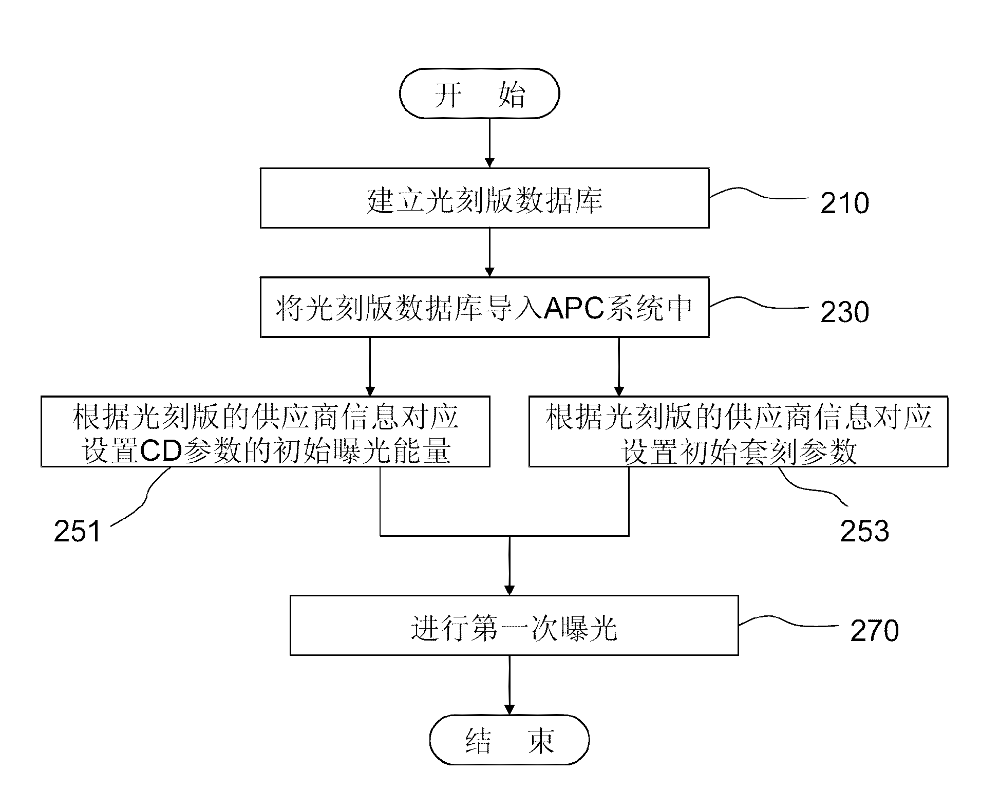
A technology of exposure conditions and photolithography, which is applied in the direction of microlithography exposure equipment, photolithography exposure device, etc., can solve the problems of mutual difference, CD difference, difference, etc., and achieve the effect of improving yield rate and reducing rework rate

Active Publication Date: 2013-07-03
CSMC TECH FAB2 CO LTD
View PDF5 Cites 5 Cited by
  • Summary
  • Abstract
  • Description
  • Claims
  • Application Information

AI Technical Summary

Problems solved by technology

[0005] However, chip manufacturers will choose multiple suppliers to supply lithography plates, especially for lithography plates of different products (one product corresponds to a set of lithography plates), even if it is completed under the same process platform, its lithography The suppliers of the photolithographic plates are usually different; at the same time, the CD testing equipment for the photolithographic plates produced by different suppliers is not matched or different from each other, even if the photolithography provided by each supplier corresponding to different products under the same process platform The CD of the lithographic plate is labeled as consistent, but in fact the CD of the lithographic plate is actually different, and this difference will be transmitted to the CD of the wafer to cause a difference

Method used


Image

  • Method for setting exposure conditions in photoetching
  • Method for setting exposure conditions in photoetching

Examples


Embodiment Construction

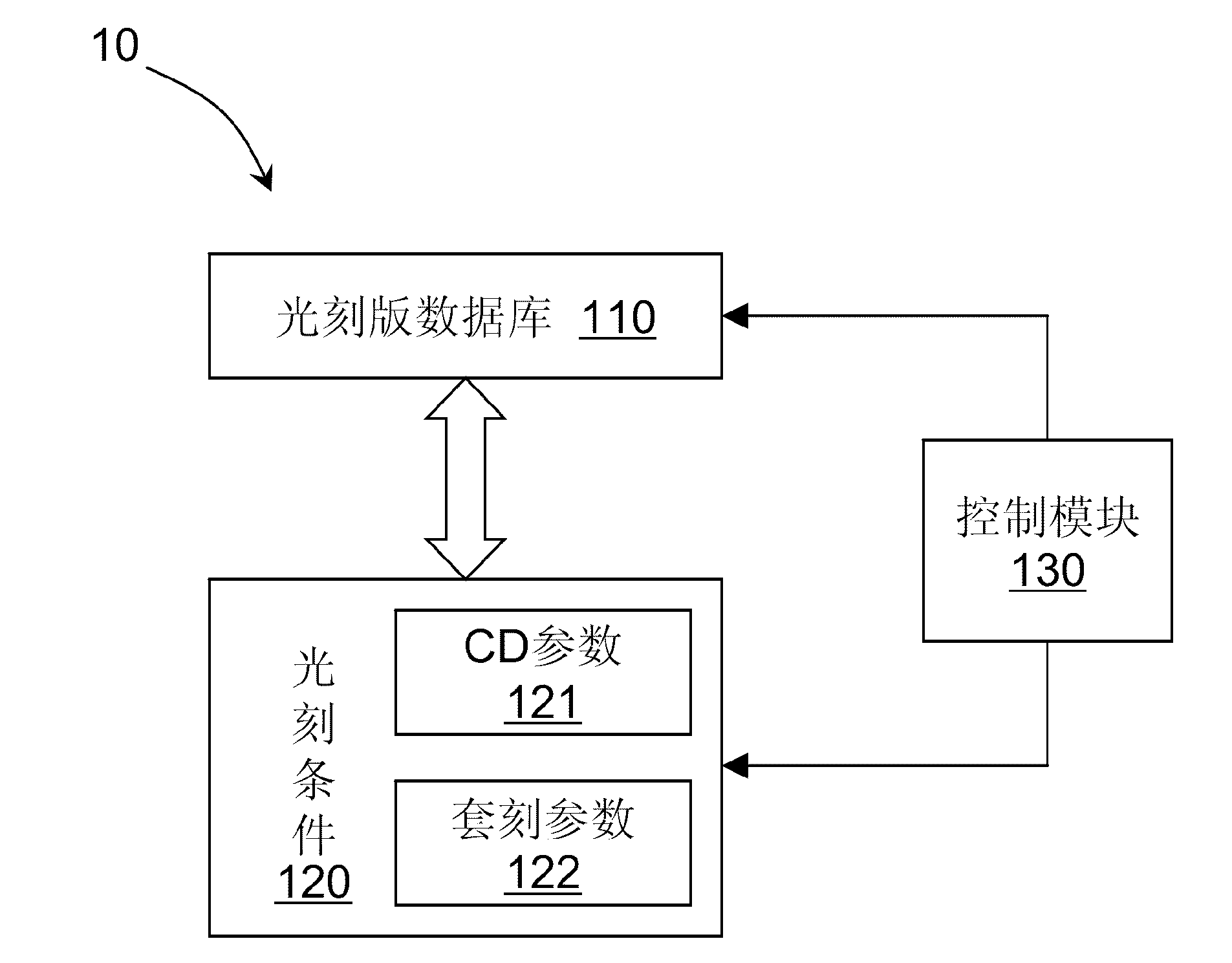
[0022] The following introduces some of the multiple possible embodiments of the present invention, which are intended to provide a basic understanding of the present invention, and are not intended to confirm the key or decisive elements of the present invention or limit the scope of protection. It is easy to understand that according to the technical solution of the present invention, without changing the essential spirit of the present invention, those of ordinary skill in the art can propose other alternative implementations. Therefore, the following specific embodiments and drawings are only exemplary descriptions of the technical solutions of the present invention, and should not be regarded as all of the present invention or as a limitation or limitation to the technical solutions of the present invention.

[0023] In this article, the lithography conditions include CD parameters and Overlay parameters. The CD parameter refers to the CD of the wafer that mainly affects lith...


PUM


Abstract

The invention provides a method for setting exposure conditions in photoetching, and belongs to the technical field of semiconductor photoetching. The method for setting exposure conditions in photoetching is applied to the first-time photoetching process of a photolithography mask used under a first process platform for the first time; and during a setting process, at least an initial exposure energy in the exposure conditions is correspondingly set according to the provider information of the photolithography mask. Therefore, the problem that the CD (compact disk) of a wafer exceeds the specific process specifications caused by no consideration for the provider difference factor of the photolithography mask is avoided, the yield of the first-time photoetching is increased, and the rework rate of the photoetching is greatly reduced.

Description

Technical field [0001] The present invention belongs to the technical field of semiconductor lithography, and relates to a method for setting exposure conditions in lithography, and in particular to a method for setting exposure conditions during the first lithography of a photolithography plate used for the first time under the same process platform. Taking into account the difference in the feature size (CD) of the wafer for the first lithography caused by the difference of the lithography plate suppliers. Background technique [0002] Photolithography is one of the main patterning methods in semiconductor manufacturing technology, in which the pattern is transferred to the photoresist of the wafer through a photolithography plate. Therefore, the photolithography plate is a common tool in the photolithography process. In the process of photolithography, the critical dimension (Critical Dimension, also known as "CD" or "feature line width") of the wafer formed by the photol...

Claims


Application Information

Patent Timeline
IPC IPC(8): G03F7/20
Inventor 黄玮
Owner CSMC TECH FAB2 CO LTD
Learn More