Split-type electric control system for numerical control cutting bed
An electronic control system, split technology, applied in the direction of digital control, electrical program control, etc., can solve the problems of reducing the service life of electrical components, low wiring efficiency, cumbersome wiring, etc., to improve efficiency, increase service life, and shorten installation the effect of time
- Summary
- Abstract
- Description
- Claims
- Application Information
AI Technical Summary
Problems solved by technology
Method used
Image

Examples
Embodiment Construction
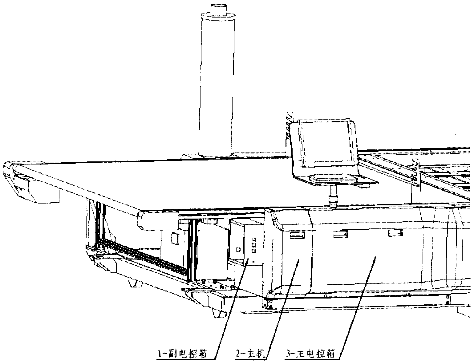
[0013] Such as figure 1 As shown, the present invention is a split-type electric control system of a CNC cutting machine, one or more low-voltage switchgear and related control, measurement, signal, protection, adjustment and other equipment, and a combination of all internal electrical and mechanical connections Body, the system includes 1-subsidiary electric control box; 3-main electric control box. The main electric control box is used to control the linear movement of the cutting bed, and is located on the right side of the main machine outer box. The auxiliary electric control box is used to control the walking and reciprocating movement of the cutting machine head, and is located on the left side of the main machine outer box. The invention has the following beneficial effects: simple structure; layout in advance can shorten the installation time and improve the efficiency of wiring; prevent signal failure caused by electromagnetic interference; overcome the ablation de...
PUM
 Abstract
Description
Claims
Application Information
 - Generate Ideas
- Intellectual Property
- Life Sciences
- Materials
- Tech Scout
- Unparalleled Data Quality
- Higher Quality Content
- 60% Fewer Hallucinations
Browse by: Latest US Patents, China's latest patents, Technical Efficacy Thesaurus, Application Domain, Technology Topic, Popular Technical Reports.
© 2025 PatSnap. All rights reserved.Legal|Privacy policy|Modern Slavery Act Transparency Statement|Sitemap|About US| Contact US: help@patsnap.com