
Charging system for electric automobile and electric automobile with same

A charging system, electric vehicle technology, applied in electric vehicles, battery circuit devices, current collectors, etc., can solve the problems of unadjustable voltage, low charging power, increased cost, etc., achieve a wide operating voltage range, save space and cost, The effect of saving time and cost

Active Publication Date: 2013-07-03
BYD CO LTD
View PDF3 Cites 23 Cited by
  • Summary
  • Abstract
  • Description
  • Claims
  • Application Information

AI Technical Summary

Problems solved by technology

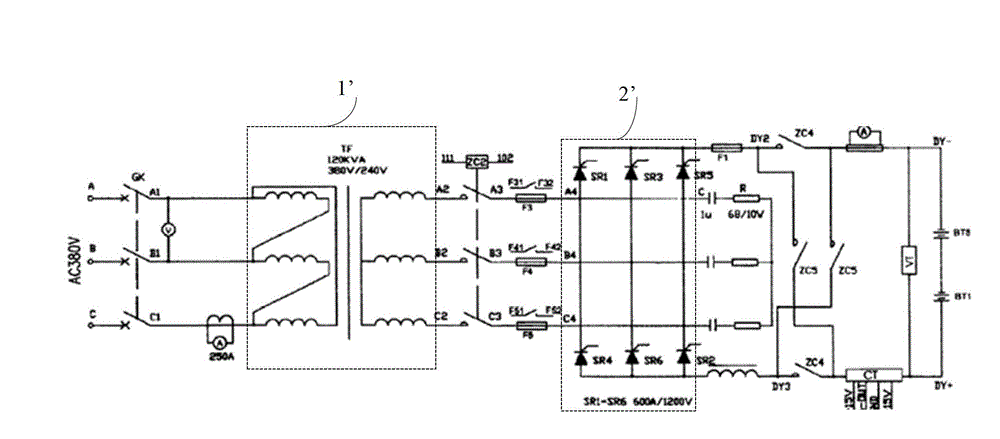
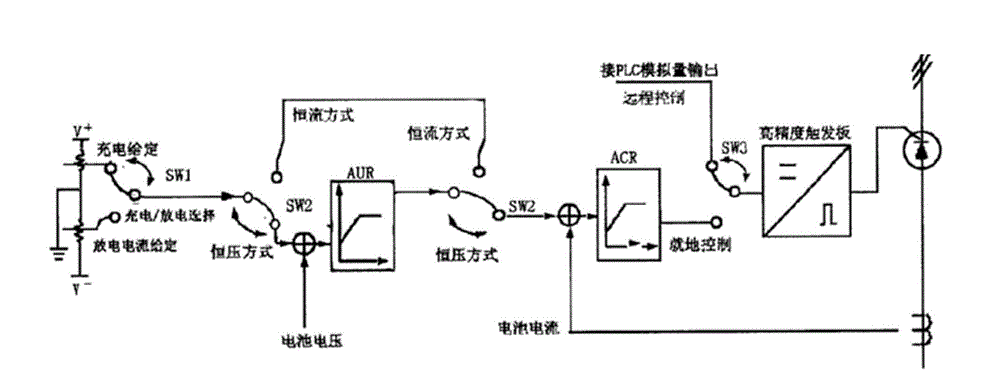
[0005] Option (1): If figure 1 and figure 2 As shown, the on-board charging and discharging device in this scheme mainly includes a three-phase power transformer 1', a three-phase bridge circuit 2' composed of six thyristor elements, a constant voltage control device AUR and a constant current control device ACR, but this scheme is seriously wasteful space and cost
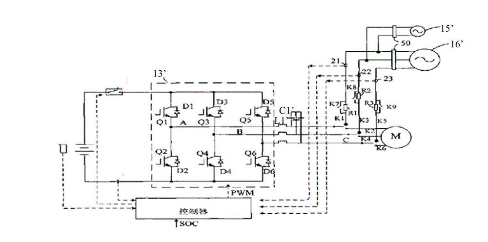
[0006] Option (2): If image 3 As shown, the on-board charging and discharging device in this scheme installs two charging sockets 15' and 16' to adapt to single-phase / three-phase charging, which increases the cost; the motor drive circuit includes a filter module composed of inductor L1' and capacitor C1', When the motor is driven, the three-phase current passes through the filter module to generate loss, which is a waste of battery power; the inverter 13' rectifies / inverts the alternating current during charging and discharging in this scheme, and the voltage cannot be adjusted after rectification / inversion, which is applicable The battery operating voltage range is narrow
[0007] To sum up, most of the current AC charging technologies on the market use a single charging technology. This technology has low charging power, long charging time, large hardware size, single function, and is limited by the voltage level of power grids in different regions. shortcoming

Method used


Image

  • Charging system for electric automobile and electric automobile with same
  • Charging system for electric automobile and electric automobile with same
  • Charging system for electric automobile and electric automobile with same

Examples


Embodiment Construction

[0043] Embodiments of the present invention are described in detail below, examples of which are shown in the drawings, wherein the same or similar reference numerals designate the same or similar elements or elements having the same or similar functions throughout. The embodiments described below by referring to the figures are exemplary only for explaining the present invention and should not be construed as limiting the present invention.

[0044] The following disclosure provides many different embodiments or examples for implementing different structures of the present invention. To simplify the disclosure of the present invention, components and arrangements of specific examples are described below. Of course, they are only examples and are not intended to limit the invention. Furthermore, the present invention may repeat reference numerals and / or letters in different instances. This repetition is for the purpose of simplicity and clarity and does not in itself indicat...


PUM


Abstract

The invention provides a charging system for an electric automobile. The charging system comprises a power battery, a first charging interface, a second charging interface, a first charging control branch circuit, a second charging control branch circuit and a controller, wherein the first and second charging interfaces are connected with an external power supply; the first charging control branch circuit is connected between the power battery and the first charging interface, and the second charging control branch circuit is connected between the power battery and the second charging interface; and the controller is connected with the first and second charging interfaces. The charging system can be used for conducting high-power alternating current charging on an electric automobile by using a civil or industrial alternating current power grid, so that a user can charge efficiently and quickly anytime and anywhere, the working voltage range for the battery is wide, and space and cost can be saved. The invention also provides the electric automobile.

Description

technical field [0001] The invention relates to the technical field of electric vehicles, in particular to an electric vehicle charging system and an electric vehicle equipped with the same. Background technique [0002] With the development of science and technology, environmentally friendly and energy-saving electric vehicles are playing the role of replacing fuel vehicles. However, the popularization of electric vehicles still faces some problems. Among them, high mileage and fast charging technology have become a major issue in the promotion of electric vehicles. problem. [0003] At present, most electric vehicles use large-capacity batteries. Although the battery life of electric vehicles can be improved, the same large-capacity batteries also bring about the problem of long charging time. Although professional DC charging stations can quickly charge batteries, the high cost and large footprint make it difficult to popularize such infrastructure. At the same time, due...

Claims


Application Information

Patent Timeline
Patent Type & Authority Applications(China)
IPC IPC(8): H02J7/00B60L11/18H02J7/02
CPCY02T10/70
Inventor 汤哲晴杜智勇唐甫
Owner BYD CO LTD
Learn More