Multifunctional medical LED (Light Emitting Diode) lighting system

An LED lighting and multifunctional technology, applied in the field of multifunctional medical LED lighting systems, can solve problems such as bulky volume and complex structure, and achieve the effects of low cost, improved reliability and simple structure

Inactive Publication Date: 2013-07-10
ZHEJIANG UNIV +1
View PDF6 Cites 9 Cited by
  • Summary
  • Abstract
  • Description
  • Claims
  • Application Information

AI Technical Summary

Problems solved by technology

At present, the narrow-band spectrum is still realized by three special

Method used


Image

  • Multifunctional medical LED (Light Emitting Diode) lighting system
  • Multifunctional medical LED (Light Emitting Diode) lighting system
  • Multifunctional medical LED (Light Emitting Diode) lighting system

Examples


Embodiment Construction

[0015] Further illustrate the present invention below in conjunction with accompanying drawing.

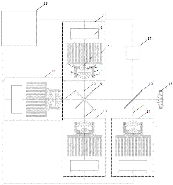
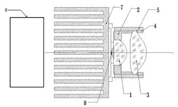
[0016] refer to figure 1 , figure 2 , the multifunctional medical LED lighting system of the present invention includes four groups of LED modules 11, 12, 13, 14 with identical dimensions, each group of LED modules includes LED chips 8, heat sinks 7, LED drive control circuit boards 6 and lens barrels 5. Install the first lens 1, the spacer ring 2, the second lens 3 and the pressure ring 4 in the lens barrel 5 in order from the rear end to the front end, and the LED chip 8 is coaxially installed at the rear end of the lens barrel 5 and fixed on the heat dissipation On the device 7, the first lens 1 is a positive lens, and its optical surface close to the LED chip 8 is concave, facing the front end of the lens barrel is a convex surface, and the second lens 3 is a positive lens, and its optical surface facing the LED chip is convex, facing the front end of the lens barrel It is ...


PUM


Abstract

A multifunctional medical LED lighting system provided by the invention comprises four groups of LED modules which are exactly the same in sizes and provided with an R chip, a G chip, a B chip and a UW chip respectively; optical collimators with identical in structures are mounted at the front parts of the light-emitting surfaces of the LED chips respectively to collimate emergent light of the LEDs; three ways of emergent light of three LEDs of R/G/B are mixed into a one-way emergent light via an X-ray plate; two ways of emergent light of two LEDs of R/UW are mixed into a one-way emergent light via a dichroic mirror; the dichroic mirror is controlled by a motor to rotate for 45 degrees; when white light is chosen for lighting, the LEDs of G/B do not emit light, the LEDs of R/UW emit light, and at the moment, a UW (cold white) light and an R (red) light are mixed to generate a white light source via the dichroic mirror; when a RGB narrow-band light source is chosen, the UW LED does not emit light, and at the moment, the LEDs of R/G/B emit light at different time; when the UW LED goes wrong, the LEDs of R/G/B emit light at the same time and can be used as the spare white light source; and a condensing lens is mounted at the front of the dichroic mirror, so that the emergent light of the light source is enabled to be coupled in light fiber optic arrays conveniently. The multifunctional medical LED lighting system is compact in structure, low in cost, high in reliability, high color rendering white light and narrow-band images.

Description

technical field [0001] The invention relates to a multifunctional medical LED lighting system. Background technique [0002] Laparoscopic surgery is a major direction of medical development in the future. Compared with traditional open surgery, it has many advantages such as less surgical trauma, less pain for patients, and faster postoperative recovery. The illumination system of the cavity mirror plays a vital role in obtaining clear and obvious intracavity images. Existing cavity mirror lighting systems mostly use gas light sources, such as xenon lamps. Its advantages are large luminous flux and good color rendering. But there are shortcomings such as short life and high energy consumption. LED light sources have the advantages of high luminous efficiency and long service life. However, when they are used in medical lighting, they have the problem of poor color rendering, that is, low color rendering index (CRI). How to improve CRI is an important issue restricting th...

Claims


Application Information

Patent Timeline
IPC IPC(8): A61B1/00
CPCA61B1/0669A61B1/0684
Inventor 王立强杨天领石岩
Owner ZHEJIANG UNIV
Why Eureka
Try Eureka