
Method, computing unit, CT system and C-arm system for reducing metal artifacts

A metal artifact, metal technology, applied in the field of C-arm system, can solve problems such as residual artifacts

Inactive Publication Date: 2013-07-10
SIEMENS HEALTHCARE GMBH
View PDF5 Cites 32 Cited by
  • Summary
  • Abstract
  • Description
  • Claims
  • Application Information

AI Technical Summary

Problems solved by technology

[0007] Although the above methods partially provide reasonably good results, there are still residual artifacts to be eliminated

Method used


Image

  • Method, computing unit, CT system and C-arm system for reducing metal artifacts
  • Method, computing unit, CT system and C-arm system for reducing metal artifacts
  • Method, computing unit, CT system and C-arm system for reducing metal artifacts

Examples


Embodiment Construction

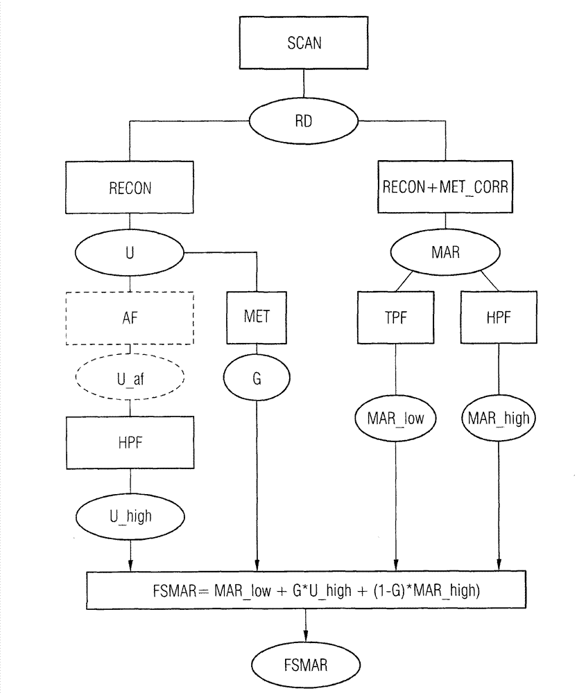
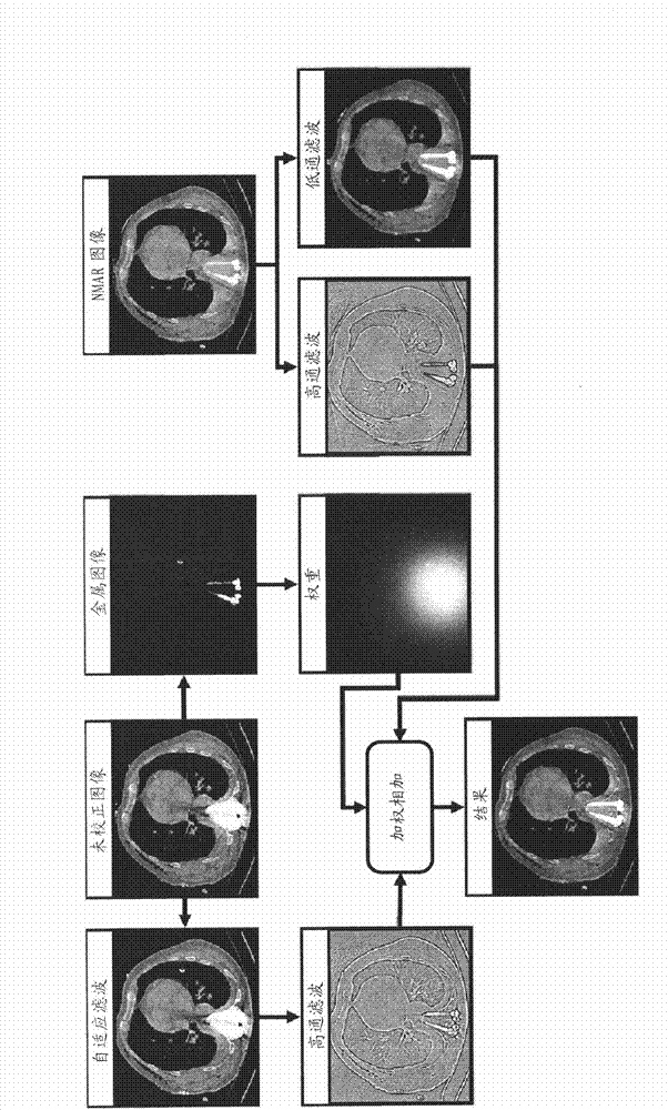
[0039] figure 1 A flow chart of the method for correcting metal artifacts according to the present invention is shown. In this case, in method step SCAN, a tomographic scan is first performed on the patient in order to obtain detector data or raw detector data RD. On the basis of the detector data, on the one hand, in method step RECON, any known reconstruction without correction for metal artifacts is then performed, from which an uncorrected (with respect to metal artifacts) CT image data set U is generated. Optionally, in method step AF, the uncorrected CT image data set U can be filtered with a noise-dependent adaptive filter, whereby an adaptively filtered CT image data set U_af is produced as a result. In method step HPF, a high-pass filter component U_high is calculated from the respective CT image data record U or U_af by using a high-pass filter.

[0040] Furthermore, in method step MET a weighting mask G is generated with the aid of the uncorrected CT image dataset...


PUM


Abstract

A method is disclosed for reducing metal artifacts in CT image datasets. An embodiment of the method includes reconstructing a first CT image dataset with and a second CT image dataset without metal artifact correction, weighted summation of a high-pass-filtered first and a high-pass-filtered second CT image dataset plus a low-pass-filtered second CT image dataset, wherein the weightings are dependent on the proximity to metal in the CT image datasets. A computing unit, a CT system and a C-arm system designed to execute the method are also disclosed.

Description

technical field [0001] The invention relates to a method, a computing unit, a CT system and a C-arm system for reducing metal artifacts in a CT image dataset. Background technique [0002] Methods for reconstructing tomographic image data sets from detector data of a scanned object by CT systems are generally known. If there are metallic objects within the object, strong image artifacts, so-called metal artifacts, are produced due to enhanced ray hardening, increased scattering, partial volume effects and amplified noise, which sensitively reduce the quality of the reconstructed image. [0003] Different methods are known to reduce such metal artifacts and they can be divided into three categories: [0004] - Interpolation methods, as described, for example, in the article "Reduction of CT artifacts caused by metallic implants" by W.A. Kalender, R. Hebel and J. Ebersberger Radiology, vol.164, no.2, pp. 576-577, Aug.1987, and the article "A new algorithm for metal artifact ...

Claims


Application Information

Patent Timeline
Patent Type & Authority Applications(China)
IPC IPC(8): A61B6/03A61B19/00G06T5/00
CPCA61B6/03A61B6/5282G06T5/50G06T11/008G06T2207/10081G06T5/73A61B6/00
Inventor M·卡彻尔里斯E·梅耶R·劳佩克
Owner SIEMENS HEALTHCARE GMBH
Learn More