
Powder metallurgical formulas for internal and external rotors of hydraulic slippage pump and manufacturing method of internal and external rotors of hydraulic slippage pump

A powder metallurgy and oil charge pump technology, applied in the field of powder metallurgy, can solve the problems of damage to main pump parts, economic losses, inconvenient maintenance work, etc., and achieve the effect of satisfying long-term load operation, reducing economic losses, and preventing impact deformation.

Inactive Publication Date: 2013-07-10
南京浩德粉末冶金有限公司
View PDF5 Cites 12 Cited by
  • Summary
  • Abstract
  • Description
  • Claims
  • Application Information

AI Technical Summary

Problems solved by technology

[0003] As the core power source of the closed system control, the charge pump, once abnormally stuck, the whole closed system will be paralyzed immediately. Closed systems are often used in construction machinery, especially cement mixer trucks. Once the control system collapses, the cement The storage tank should stop running immediately. If it cannot be repaired and replaced in time, the cement in the tank will be solidified, and the cement storage tank will be scrapped.
The power shaft of the charge pump and the power shaft of the main pump are in series structure, that is, once the charge pump gets stuck, it will inevitably affect the main pump. If effective measures cannot be taken to remove the blocking resistance in time, the main pump will directly cause zero Damage to components, which will bring great inconvenience to maintenance work and cause unnecessary economic losses

Method used

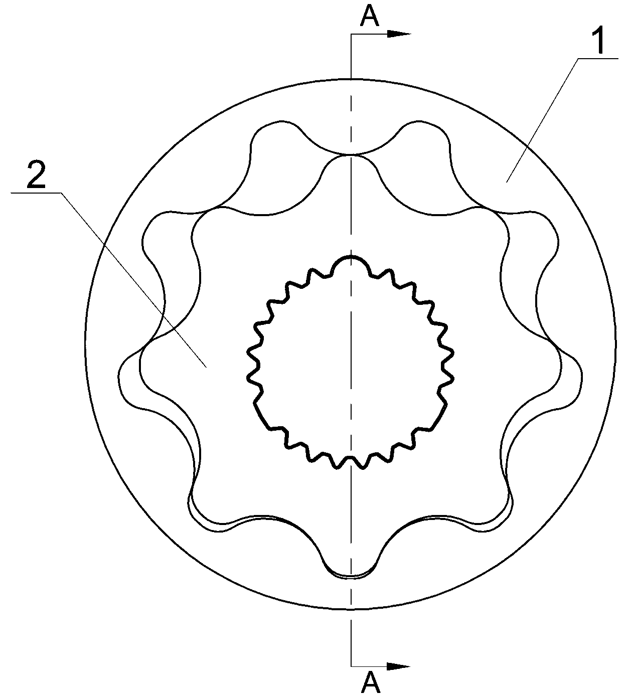
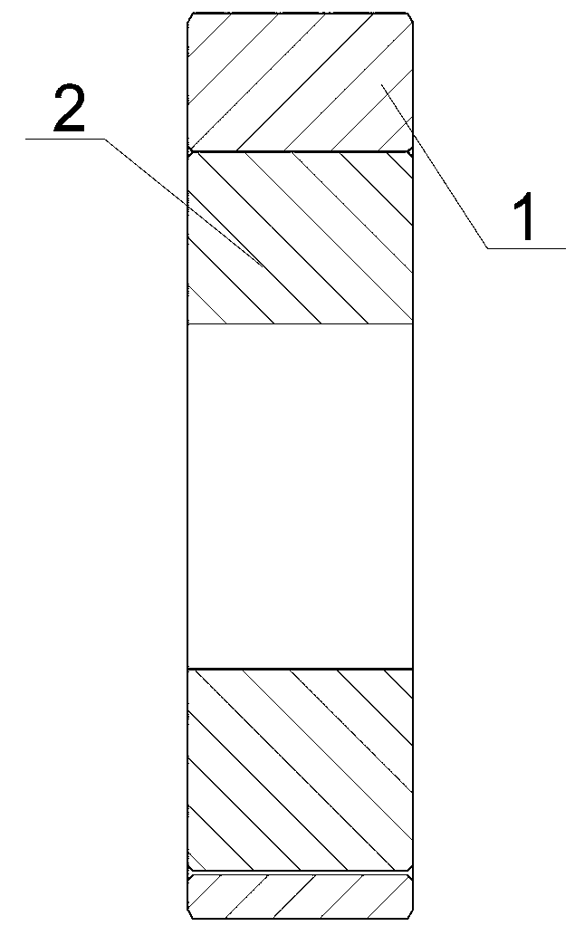

Image

  • Powder metallurgical formulas for internal and external rotors of hydraulic slippage pump and manufacturing method of internal and external rotors of hydraulic slippage pump
  • Powder metallurgical formulas for internal and external rotors of hydraulic slippage pump and manufacturing method of internal and external rotors of hydraulic slippage pump

Examples


Embodiment Construction

[0028] In order to make the technical means, creative features, goals and effects achieved by the present invention easy to understand, the present invention will be further described below in conjunction with specific illustrations.

[0029] The powder metallurgy formula of the inner and outer rotors of the hydraulic charge pump, according to the actual working conditions and the structural force analysis of each component, the powder metallurgy formula of the inner rotor and the outer rotor adopts two different formulas, and is equipped with different heat treatment processes to meet actual needs. , which can not only meet the needs of conventional working conditions, but also solve the problems in the technical background. The specific raw material ratio is as follows:

[0030] Inner rotor: carbon 0.7-0.9%, nickel 2-3%, copper 1.5-2.5%, the balance is iron powder;

[0031] Outer rotor: carbon 0.5-0.8%, nickel 0.5-1.8%, molybdenum 2-3%, manganese 2-3%, and the balance is iro...


PUM


Abstract

The invention relates to powder metallurgical formulas for internal and external rotors of a hydraulic slippage pump. According to actual working conditions and structural stress analysis on every part, two different formulas are adopted in the powder metallurgical formulas of the internal and external rotors, wherein powder for the internal rotor comprises 0.7-0.9% of carbon, 2-3% of nickel, 1.5-2.5% of copper and the balance iron powder; and the powder for the external rotor comprises 0.5-0.8% of carbon, 0.5-1.8% of nickel, 2-3% of molybdenum, 2-3% of manganese and the balance iron powder. The manufacturing method of the internal and external rotors of the hydraulic slippage pump includes: compressing, sintering, tempering, half finely processing, chamfering, finely reforming, finely processing, polishing for burring, cleaning and anti-corrosion processing. The internal rotor and the external rotor are manufactured according to the different formulas, defect of cycloid internal and external rotors of an existing slippage pump is effectively overcome, and the manufactured internal and external rotors are resistant to high temperature, abrasion and impact and is long in service life, and can meet requirements on long-time on-load operation and avoid damages to a main pump and other parts.

Description

technical field [0001] The invention relates to the technical field of powder metallurgy, in particular to a powder metallurgy formula and a manufacturing method for inner and outer rotors of a hydraulic charge pump. Background technique [0002] Powder metallurgy is a processing method in which metal powder or a mixture of non-metallic powder is made into products by pressing, sintering and solidification. High precision meets the needs of design and use, saves man-hours, avoids unnecessary margin processing, and greatly reduces production costs. The cycloidal inner and outer rotors of the charge pump are used for the servo control of the modern high-pressure plunger pump and the hydraulic oil circulation cooling of the closed-loop system. High temperature and high pressure resistance, wear resistance, impact resistance, long life, and long-term load operation require extremely high requirements for the manufacturing process of the inner and outer rotors. [0003] The cha...

Claims


Application Information

Patent Timeline
IPC IPC(8): B22F1/00C22C38/16C22C38/12F04C2/10
Inventor 张祝吴斯灏陈力航贾中仁
Owner 南京浩德粉末冶金有限公司
Learn More