Automatic clutch control system

An automatic clutch and clutch control technology, applied to clutches, mechanical equipment, etc., can solve problems such as high cost, offset of working cylinder load characteristics, poor system stability, etc., and achieve the effect of simple structure, low cost and reliable operation

Active Publication Date: 2013-07-10
JIANGXI B ENERGY SHANGRAO COACH
View PDF8 Cites 8 Cited by
  • Summary
  • Abstract
  • Description
  • Claims
  • Application Information

AI Technical Summary

Problems solved by technology

The disadvantage is that due to the increase of the hydraulic system, the system is relatively complicated and the cost is high, and usually due to the use of high-frequency electromagnetic switching valves, etc., the system stability is poor
At the same time, in some hydraulic systems, it usually uses the position switch signal fixed on the clutch actuator cylinder, or the angle signal of the release fork to judge and control the engagement of the clutch. If the load characteristic of the working cylinder deviates after work or due to overtime work, its stability is not high
Others use motor plus hydraulic mechanism, and design a special hydraulic system to drive the clutch release bearing. The advantage is that it replaces the traditional mechanical fork mechanism and saves layout space. The disadvantage is that a special ball screw system is designed, and the release bearing The design of the hydraulic cylinder is very difficult. Due to the limited space in the clutch housing and the small axial dimension, the guiding function of the hydraulic cylinder cannot be realized. The mechanism is complicated and the cost is high, so it cannot be realized in the short term.

Method used


Image

  • Automatic clutch control system
  • Automatic clutch control system

Examples


Embodiment Construction

[0021] In order to understand the technical content of the present invention more clearly, the following examples are given in detail.

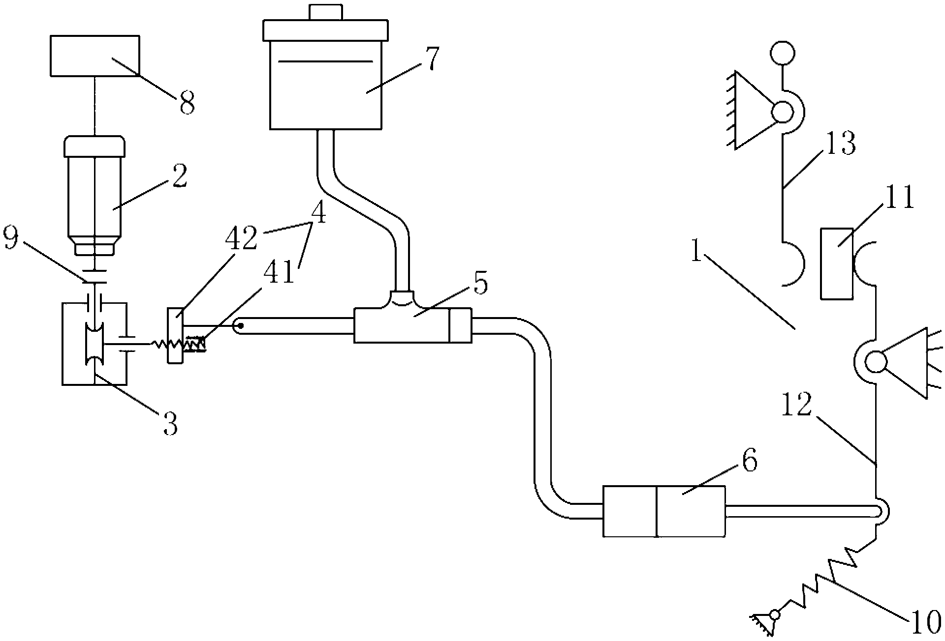
[0022] See figure 1 As shown, the automatic clutch control system of the present invention includes a clutch 1, a motor 2, a speed reducer 3, a transmission element 4, a clutch control master cylinder 5, a working cylinder 6, a fluid source 7 and a control device 8, and the motor 2 passes through the The reducer 3 is connected to the transmission element 4, and the transmission element 4 is connected to the piston rod of the clutch operation master cylinder 5 for pushing the piston rod of the clutch operation master cylinder 5 to move, and the fluid source 7 passes through the The clutch control master cylinder 5 is in fluid communication with the working cylinder 6, the piston rod of the working cylinder 6 is connected to the release fork 12 of the clutch 1 for pushing the release fork 12 to move, and the control device 8 is connected to the...


PUM


Abstract

The invention relates to an automatic clutch control system which comprises a clutch, a motor, a speed reducer, a transmission element, a main clutch control cylinder, a working cylinder, a fluid source and a control device. The motor is connected with the transmission element through a speed reducer, the transmission element is connected with a piston rod of the main clutch control cylinder and used for pushing the piston rod to move, the fluid source is communicated with the working cylinder through the main clutch control cylinder, a piston rod of the working cylinder is connected with a release fork of the clutch to push the release fork to move, and the control device is in signal connection with the motor. Preferably, the speed reducer is a worm-gear reducer, the transmission element is a cam mechanism or screw transmission mechanism, and two clutch rotating-speed detecting devices are positioned at two ends of the clutch respectively to detect rotating speeds of the two ends of the clutch, and are in signal connection with the control device. The automatic clutch control system is ingenious in design, suitable for controlling of automatic clutches of hybrid electric vehicles, compact in structure, reliable in operation, low in cost and suitable for wide popularization and application.

Description

technical field [0001] The invention relates to the technical field of hybrid electric vehicles, in particular to the technical field of automatic clutches for hybrid electric passenger cars, in particular to an automatic clutch control system applicable to hybrid electric vehicles. Background technique [0002] In the existing traditional car field, there is an automatic clutch system ACS used for manual transmission car modification. Its technology originated in Germany. The automatic clutch technology has been used in Mercedes-Benz A190, C230, BMW M3, Ferrari, F1 racing cars, etc., and its application has been very high. Mature. At present, the domestic automatic clutch technology was first introduced from overseas by Hong Kong Dongyuan Global Group. Its working principle is mainly an independent system that realizes automatic control of clutch separation and combination through machinery, electronics, and hydraulic pressure. It is composed of clutch drive mechanism, cont...

Claims


Application Information

Patent Timeline
Patent Type & Authority Applications(China)
IPC IPC(8): F16D48/06
Inventor 姚杰李剑张洪川
Owner JIANGXI B ENERGY SHANGRAO COACH
Why Eureka
Try Eureka