
Object vibration spectrum measurement system based on laser

A vibration spectrum and measurement system technology, which is applied to measurement devices, ultrasonic/sonic/infrasonic waves, instruments, etc., can solve the problems that the acoustic wave method is susceptible to environmental interference and measurement errors, and achieves strong anti-interference ability and good stability. , the effect of real-time storage and reading

Inactive Publication Date: 2013-07-10
SICHUAN UNIV
View PDF0 Cites 10 Cited by
  • Summary
  • Abstract
  • Description
  • Claims
  • Application Information

AI Technical Summary

Problems solved by technology

[0003] In order to overcome the measurement error caused by the vibration of the sensor along with the object in the contact vibration measurement technology or the problem that the acoustic wave method in the non-contact vibration measurement technology is susceptible to environmental interference, the invention provides a device that uses laser triangulation Vibration measurement technology belongs to long-distance non-contact measurement. This technology has the advantages of strong anti-interference and good stability. In addition, the device can also store the vibration information of objects in the form of data, and restore the vibration information when necessary.

Method used


Image

  • Object vibration spectrum measurement system based on laser
  • Object vibration spectrum measurement system based on laser
  • Object vibration spectrum measurement system based on laser

Examples


Embodiment Construction

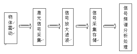
[0011] figure 1 It means that the system is mainly composed of four parts: signal acquisition, signal filtering and amplification, signal sampling and storage, and signal transformation.

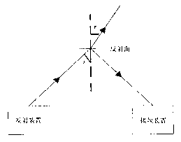
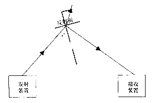
[0012] exist figure 2 with image 3 In , it means that when the measured object vibrates, the vibration causes the incident angle of the laser to change under the condition that the incident direction remains unchanged. The reflection law and refraction law of light are used to deduce the reflected laser Poynting vector as The angle of incidence changes so that the reflected laser light is modulated by the vibrations of the object.

[0013] Figure 4 Represents the signal acquisition part of the circuit, where LED1 and LED2 represent photocells respectively, and their positions are placed at 45 degrees to each other. The two photocells convert optical signals into electrical signals. Three OPA2107 constitute a precision instrument amplifier circuit (equivalent to AD620), and differentia...


PUM


Abstract

The invention provides a device for carrying out spectrum measurement on a vibration object by utilizing the laser triangle vibration measurement technology. The measurement mode belongs to the long-distance non-contact measurement mode and is characterized by high precision, high interference resistance and extending stability. The object vibration spectrum measurement system based on the laser mainly comprises a signal acquiring part, a signal processing part and a spectrum analyzing part; the signal acquiring part has the operating principle that a stable focusable laser generator is adopted for generating the laser, and the laser is irradiated on a vibration object to be measured; two photoelectric cell sensors are arranged at 45 degrees from each other and are used for receiving the reflected laser with the object vibration information, as well as implementing photovoltaic conversion; the signal processing part has the operating principle that an AD620 precision instrument amplifier, an NE5532 optional amplifier and a Cortex-M4 single chip microcomputer are adopted for carrying out differential amplification, filter and amplification and AD sampling and storing on the converted electric signal; and the spectrum analysis part has the operating principle that the Cortex-M4 single chip microcomputer is utilized for carrying out FFT (Fast Fourier Transform Algorithm) on the sampled signal so as to obtain a frequency domain signal, and displaying the frequency domain distribution data in a graphic form by utilizing a display. By adopting the object vibration spectrum measurement system based on the laser, a user can conveniently see the vibration information of the measured object.

Description

technical field [0001] The invention relates to a device for measuring the frequency spectrum of a vibrating object by using laser triangular vibration technology. In addition, the device can also store and restore the vibration information of the object. Background technique [0002] The measurement and analysis of vibration characteristics is an important means to identify and determine the reliability of machines and components; the commonly used vibration measurement technology is contact measurement; an acceleration sensor is installed on the measured object, and the acceleration sensor’s charge output signal is used to achieve acceleration- Velocity-displacement related measurement; if the vibration of an object with a small mass is measured, the quality of the additional acceleration sensor will often affect the vibration of the measured object, resulting in measurement errors; design and develop a new type of non-contact, high-precision, real-time Vibration measureme...

Claims


Application Information

Patent Timeline
IPC IPC(8): G01H9/00
Inventor 俞磊李路长李金炳何美玲牟南历冯国英
Owner SICHUAN UNIV
Learn More