
Anti-overflow device of magnetic liquid micro differential pressure transducer

A micro differential pressure sensor, magnetic liquid technology, applied in measuring devices, measuring fluid pressure, instruments, etc., can solve the problems of overflow of magnetic liquid, distortion of measurement results, environmental pollution, etc.

Inactive Publication Date: 2015-02-25
BEIJING JIAOTONG UNIV
View PDF4 Cites 0 Cited by
  • Summary
  • Abstract
  • Description
  • Claims
  • Application Information

AI Technical Summary

Problems solved by technology

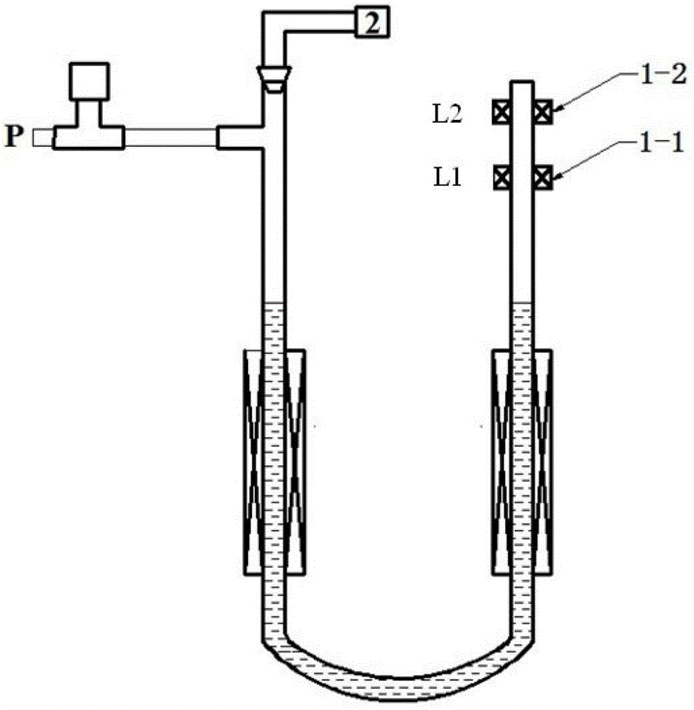
[0003] Since one side of the U-shaped plexiglass tube of the magnetic liquid differential pressure sensor is connected to the atmosphere, when the pressure source P is pressurized, if P exceeds the critical value, the magnetic liquid will flow from the U-shaped plexiglass tube to the atmosphere. The connected side overflows, causing environmental contamination and distortion of measurement results

Method used


Image

  • Anti-overflow device of magnetic liquid micro differential pressure transducer
  • Anti-overflow device of magnetic liquid micro differential pressure transducer
  • Anti-overflow device of magnetic liquid micro differential pressure transducer

Examples


Embodiment Construction

[0018] The present invention will be further described with accompanying drawing as specific embodiment:

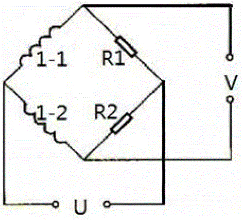
[0019] An anti-overflow device for a magnetic liquid micro-pressure differential sensor, such as figure 1 , 2 , 3 shown. The device includes: high-strength enamelled copper coil first coil 1-1 (L1) and second coil 1-2 (L2), first sliding rheostat R1 and second sliding rheostat R2, AC power supply U, voltmeter V, A / D analog-to-digital converter, 8031 ​​single-chip microcomputer, motor and worm gear structure 2;

[0020] The high-strength enamelled copper wire is evenly wound on the upper right arm of the U-shaped plexiglass tube of the magnetic liquid micro-pressure difference sensor to form the first coil 1-1 and the second coil 1-2, and the distance between the two coils is 10mm ;

[0021] After the first coil 1-1 and the second coil 1-2 are respectively connected in series with the first sliding rheostat R1 and the second sliding rheostat R2, they are connected in p...


PUM


Abstract

The invention relates to an anti-overflow device of a magnetic liquid micro differential pressure transducer, and belongs to an auxiliary device of the magnetic liquid micro differential pressure transducer. The anti-overflow device of the magnetic liquid micro differential pressure transducer is suitable for measuring magnetic liquid micro differential pressure. The anti-overflow device of the magnetic liquid micro differential pressure transducer solves the problems of environmental pollution and distortion of a measuring result, wherein the problems are caused by magnetic liquid overflow when pressure exceeds a critical value. The anti-overflow device comprises a high-strength enamelled copper coil L1 (1-1), a high-strength enamelled copper coil L2 (1-2), a sliding rheostat R1, a sliding rheostat R2, an alternating current power source U, a voltmeter V, an analog-to-digital (A / D) converter, an 8031 singlechip, a motor and a worm and gear structure (2). The high-strength enamelled copper coil L1 (1-1) and the high-strength enamelled copper coil L2 (1-2) are evenly wound on the upper portion of the right arm of a U-shaped organic glass tube of the magnetic liquid micro differential pressure transducer with equal number of turns to form coils. One coil is connected with the equivalent sliding rheostat R1 in series, the other coil is connected with the equivalent sliding rheostat R2 in series, and then the coils are connected at two ends of the alternating power source U in parallel. A voltage signal output by a bridge circuit passes the A / D converter and then the 8031 singlechip controls the motor to rotate to drive the worm and gear structure to move upwards, therefore, a rubber tube is moved out of the U-shaped tube, and a liquid level inside the U-shaped tube gets back to a balancing position again.

Description

technical field [0001] The invention belongs to an auxiliary device of a magnetic liquid micro-pressure difference sensor, and is particularly suitable for the field of magnetic liquid micro-pressure difference measurement. Background technique [0002] At present, the research on the magnetic liquid micro-pressure difference sensor in our country is still in the experimental stage. The principle is as follows: the U-shaped plexiglass tube is equipped with a magnetic liquid, the two arms are wound with a coil and connected to an alternating current, and the external circuit resistance forms a bridge circuit. When the difference is applied, the liquid surface of the two arms of the U-shaped plexiglass tube produces a height difference Δh, and then the coil inductance L changes, and the balance of the bridge is destroyed. The voltage change measured by the external circuit is used to obtain the pressure difference change. [0003] Since one side of the U-shaped plexiglass tube...

Claims


Application Information

Patent Timeline
Patent Type & Authority Patents(China)
IPC IPC(8): G01L19/00
Inventor 谢君李德才
Owner BEIJING JIAOTONG UNIV
Learn More