Radar moving target detection method based on cognitive framework

A moving target detection and radar technology, applied in the field of moving target detection, can solve the problems of unsatisfactory detection performance in strong clutter areas, declining detection performance, and limiting the number of estimated samples.

Active Publication Date: 2013-07-10
XIDIAN UNIV
View PDF6 Cites 13 Cited by
  • Summary
  • Abstract
  • Description
  • Claims
  • Application Information

AI Technical Summary

Problems solved by technology

But on the one hand, because such a processor has to pass through an MTI filter first, when the Doppler frequency of the target falls near the notch of this filter, especially when the notch of the MTI filter is wide, the target component may be is filtered out, resulting in missed detection of the target; on the other hand, when the processor performs constant false alarm detection on a certain detection unit, it must first estimate the interference level power at this detection unit, and the selected estimation is required when estimating The samples are independent and identically distributed, but in practice, since the distribution of clutter along the distance dimension generally changes drastically, the reference unit can only be selected on both sides of the detection unit as the estimated sample of the interference level , which greatly limits the number of estimated samples, and the false alarm loss of CA-CFAR detection is related to the number of reference units. The more reference units, the less constant false alarm loss
Therefore, although this type of processor has the advantages of simple structure and fast operation speed, its detection performance in the strong clutter area is not very ideal, especially in the strong clutter background, the detection performance of low-speed targets is declining rapidly

Method used


Image

  • Radar moving target detection method based on cognitive framework
  • Radar moving target detection method based on cognitive framework
  • Radar moving target detection method based on cognitive framework

Examples


Embodiment Construction

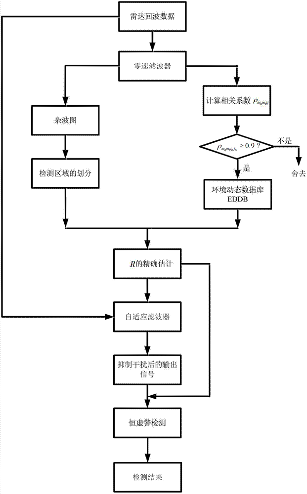
[0030] refer to figure 1 and figure 2 , the specific implementation steps of the present invention are as follows:

[0031] Step 1. Obtain the ground clutter component in the echo data through the zero-speed filter.

[0032] make x mip Indicates the echo data of the i-th azimuth angle p-th range unit in the m-th frame of the radar, where 1≤m≤m 0 , 1≤i≤I, 1≤p≤D, m 0 Indicates the current frame number, I indicates the number of radar azimuths in each frame, D indicates the number of distance units in each azimuth, h 0 Represents a zero-speed filter whose coefficients are all 1;

[0033] Obtain the ground clutter component y in the echo data through the zero-speed filter mip for: where T stands for transpose.

[0034] Step 2, generate the current frame m 0 clutter diagram.

[0035] According to the ground clutter component y of the i-th azimuth angle in the m-th frame and the p-th distance unit mip , get the current frame m 0 Estimated value of the interference leve...


PUM


Abstract

The invention discloses a radar moving target detection method based on a cognitive framework. The radar moving target detection method mainly solves the problem that in the strong clutter background, an existing method is poor in detection performance for a low-speed target. The achieving process comprises the following steps of separating ground clutter components from backward waves; obtaining a clutter image of a current frame according to the ground clutter components; sensing the environment according to the clutter image and separating the current frame into a noise region and a clutter region; calculating coefficients of associations according to the ground clutter components, utilizing the coefficients of associations to correct antenna pointing errors, and storing backward wave data after corrected to an environment dynamic data bank (EDDB); and utilizing the backward wave data of the EDDB to estimate an interference covariance matrix according to division of the current frame; obtaining a self-adaption filter coefficient according to the estimated interference covariance matrix, and conducting self-adaption filtering processing on input data; and conducting constant false alarm detection on output of a filter. The radar moving target detection method has the advantage of greatly improving detection performance under the condition that an existing device is not greatly changed, and can be used for conducting detection on the low-speed target in the strong clutter background.

Description

technical field [0001] The invention belongs to the technical field of radar, relates to moving target detection, and can be used to improve the detection performance of radar for low-speed targets under strong clutter background. technical background [0002] As a widely used battlefield sensor, battlefield surveillance radar has the advantages of all-weather, long detection distance and wide surveillance range compared with other battlefield sensor materials. However, battlefield surveillance radars have to detect moving targets, even low-speed targets, in complex ground object backgrounds and slow-moving meteorological backgrounds, which poses a huge challenge to signal processing. The traditional radar moving target detection technology generally makes the video input signal pass through an MTI filter to suppress the ground clutter component in the echo data, and then performs FFT transformation on the output signal of the MTI filter along the slow time. Here, the FFT t...

Claims


Application Information

Patent Timeline
Patent Type & Authority Applications(China)
IPC IPC(8): G01S7/41
Inventor 刘宏伟方明戴奉周赵永波纠博
Owner XIDIAN UNIV
Why Eureka
Try Eureka