Remote sensing image radiation correction method

A remote sensing image and radiometric correction technology, applied in the field of remote sensing image processing, can solve problems such as over-correction

Active Publication Date: 2013-07-10
BEIJING RES CENT FOR INFORMATION TECH & AGRI
View PDF3 Cites 28 Cited by
  • Summary
  • Abstract
  • Description
  • Claims
  • Application Information

AI Technical Summary

Problems solved by technology

[0006] Aiming at the problem of over-correction in radiation correction, the present invention provides a remote sensing image radiation correction method capable of extracting more accurate surface reflectance from remote sensing images

Method used


Image

  • Remote sensing image radiation correction method
  • Remote sensing image radiation correction method
  • Remote sensing image radiation correction method

Examples


Embodiment 1

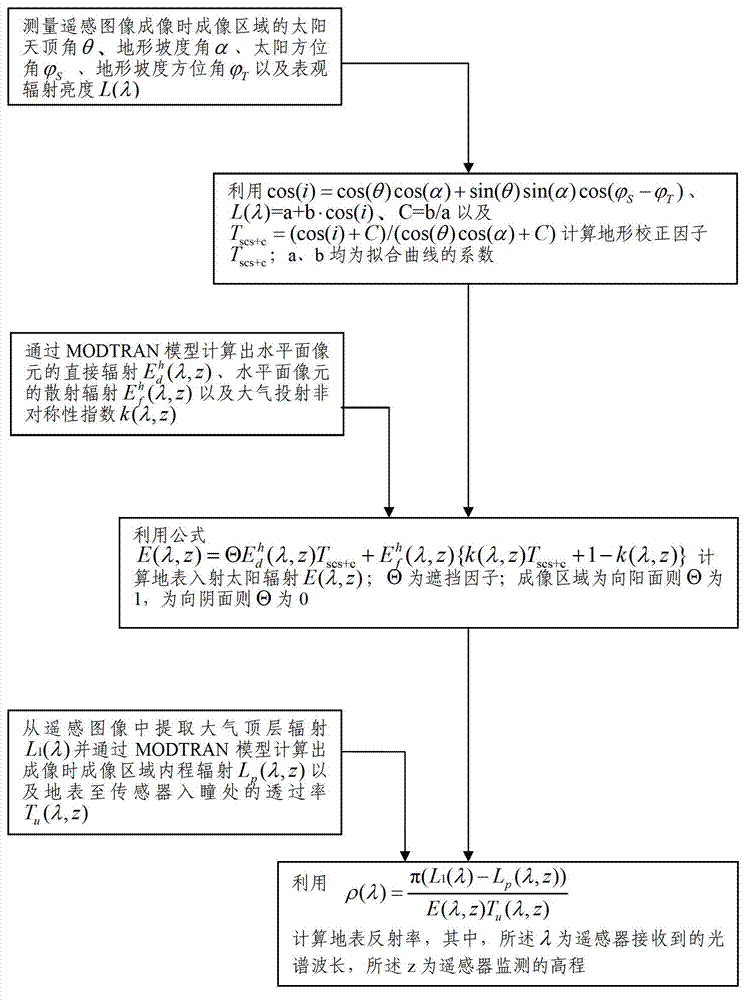
[0031] Such as figure 1 As shown, the remote sensing image radiation correction method in this embodiment includes the following steps:

[0032] Measure the solar zenith angle θ, terrain slope angle α, and solar azimuth angle of the imaging area terrain slope azimuth And the apparent radiance L(λ) of the terrain relief area;

[0033] use the formula L(λ)=a+b cos(i), C=b / a and T scs+c =(cos(i)+C) / (cos(θ)cos(α)+C) Calculate terrain correction factor T scs+c ; i is the relative incidence angle of the sun in the imaging area; a and b are the values ​​of a and b that can be calculated by linear regression;

[0034] Calculation of direct radiance of horizontal plane pixel by MODTRAN model Diffuse radiance of cells in the horizontal plane and the atmospheric projection asymmetry index k(λ, z);

[0035] use the formula E ( λ , z ) = Θ E d...

Embodiment 2

[0042] The radiometric correction method for remote sensing images in this embodiment includes the following steps:

[0043] Measure the solar zenith angle θ, terrain slope angle α, and solar azimuth angle of the imaging area and terrain slope azimuth And the apparent radiance L(λ);

[0044] use L(λ)=a+b cos(i), C=b / a, T scs+c =(cos(i)+C) / (cos(θ)cos(α)+C) Calculate terrain correction factor T scs+c ;

[0045]Calculate the direct radiance of the horizontal plane pixels in the imaging area by the MODTRAN model (atmospheric radiative transfer model) and the diffuse radiation of the pixels in the horizontal plane Atmospheric projection asymmetry index k(λ, z) and average reflectance ρ of the imaged area adj ;

[0046] where the average reflectance ρ of the imaging area is calculated adj The process is as follows: remove the influence of atmospheric diffuse radiation and path radiation in the radiation of the top layer of the atmosphere (note: atmospheric diffuse radi...

Embodiment 3

[0060] In order to further optimize the calculation of the surface reflectance to achieve the purpose of improving the accuracy of remote sensing images, this embodiment introduces the sky visibility factor V on the basis of any of the above-mentioned embodiments d and terrain visibility factor V t ,details as follows:

[0061] by formula Calculate V d ,

[0062] by formula Calculate V d , due to the introduction of V d and V t but

[0063] E ( λ , z ) = Θ E d h ( λ , z ) T scs + c E f h ( λ , z ) { k ( ...


PUM


Abstract

The invention discloses a remote sensing image radiation correction method which includes the steps of measuring a solar zenith angle theta, a topographic slope angle alpha, a solar azimuth, a topographic slope azimuth and earth surface radiance L (lambada) of an imaging area when a remote sensing image is imaged, calculating a topographical correction factor Tscs+c, calculating direct radiation, scattered radiation of a horizontal plane pixel and an atmospheric projection asymmetry index k (lambada, z) through a MODTRAN model, calculating earth surface incidence solar radiation E (lambada, z), extracting atmospheric top layer radiation L1 (lambada) from the remote sensing image, working out path radiation Lp (lambada, z) of the imaging area and transmittance Tu (lambada, z) from the earth surface to a pupil-inlet position of a sensor through the MODTRAN model, and obtaining earth surface reflectance rho (lambada), wherein the lambada is a spectral wavelength received by a remote sensor and the z is an elevation monitored by the remote sensor.

Description

technical field [0001] The invention relates to the field of remote sensing image processing, in particular to a radiation correction method for remote sensing images. Background technique [0002] Factors affecting remote sensing image imaging in remote sensing monitoring include atmospheric factors, terrain factors (especially in mountainous areas, where the impact of terrain factors is more obvious), etc.; Consistency, often requires radiometric correction of measurements extracted from remote sensing imagery generated by the acquisition to extract accurate surface reflectance values. [0003] However, in traditional remote sensing image radiation correction methods, it is generally considered based on the geometric relationship between the sun-surface-sensor, such as cosine correction, C correction, etc., only considers the direct radiation part of the imaging area, and does not take into account Scattered radiation and adjacent pixel reflected radiation, so there is a ...

Claims


Application Information

Patent Timeline
Patent Type & Authority Applications(China)
IPC IPC(8): G06K9/32
Inventor 杨贵军赵春江冯海宽宋晓宇顾晓鹤杨小冬徐新刚杨浩杨月英
Owner BEIJING RES CENT FOR INFORMATION TECH & AGRI
Why Eureka
Try Eureka