Switching device with amplified clearance between open contacts according to needs

A contact opening distance and switching device technology, which is applied in the contact driving mechanism and other directions, can solve the problems of large volume and energy consumption of the electromagnetic mechanism, reduced product life, large driving force, etc., and achieves reasonable layout of the force system and increased contact The effect of head distance and force concentration

Active Publication Date: 2013-07-10
ZHEJIANG CHINT ELECTRIC CO LTD
View PDF7 Cites 1 Cited by
  • Summary
  • Abstract
  • Description
  • Claims
  • Application Information

AI Technical Summary

Problems solved by technology

In order to obtain better breaking capacity and larger control capacity, at present, most of the contactors on the market adopt a direct drive method in which the electromagnetic mechanism directly drives the moving contact to move linearly, and the moving contact of the contact system usually adopts double contacts. The structural form of the moving contact bridge, this kind of direct-acting contactor has the following defects: First, because the design requires a large stroke of the moving contact to move in a straight line, there must be a gap between the moving contact and the static contact of the direct-acting contactor. Keep a large enough opening distance, and the stroke ratio determined by the direct drive method can only be 1:1, so the stroke of the moving iron core of the electromagnetic mechanism is also large, resulting in the energy loss of the double-coil electromagnetic mechanism in the on state. High consumption, complex structure, difficult to replace, high cost
Second, the driving force provided by the electromagnetic mechanism for the moving iron core is large, and the large impact force not only causes excessive vibration and noise during the connection / breaking process of the contact system, but also causes the volume and energy consumption of the electromagnetic mechanism to be large. reason
Third, since the moving direction of the moving iron core of the electromagnetic mechanism is consistent with the moving direction of the moving contact of the contact system, the ratio of length, width and height of the contactor product is unbalanced, which is not conducive to the miniaturization of the product
Fourth, the direct drive method is difficult to intervene in multivariate control, and cannot meet the needs of modern switchgear for the development of multi-functional contactor technology such as circuit breakers
Since the work done by the electromagnetic mechanism on the driving contact system cannot be reduced, this patent objectively does not contribute to solving the problem of "the electromagnetic mechanism is large in size and energy consumption, and there is corresponding power loss and heat radiation". On the contrary, the electromagnetic An increase in the electromagnetic driving force of the mechanism (especially in the case of a 5-fold increase) leads to a decrease in the mechanical performance of the electromagnetic mechanism and contact system and / or increases manufacturing difficulties
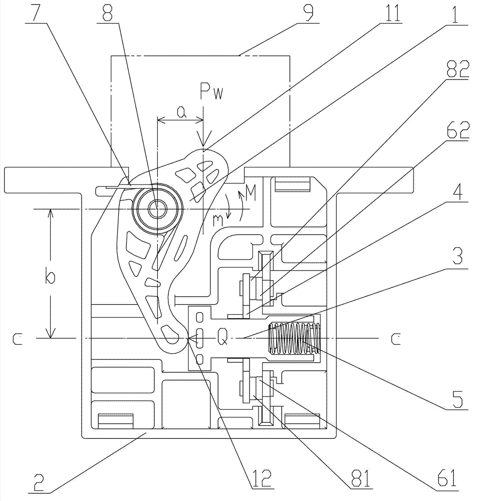
Moreover, since the pressure on the active end of the rocker arm can only come from the electromagnetic mechanism located above the active end, the pressure on the active end of the rocker arm can only make the active end move from top to bottom, and this movement can only drive the passive end and the contactor. The head support moves from bottom to top. Therefore, if the patent wants to achieve "when the active end of the rocker arm is pressed, its passive end drives the contact support to move downward", it is necessary to add a steering mechanism with driving force, and a steering mechanism with additional driving force will inevitably lead to more complex structures
In addition, when the moving contact bridge is in contact with the static contact, since the active end of the rocker arm is pressed (that is, the electromagnetic mechanism exerts pressure on the active end of the rocker arm), as long as the electromagnetic mechanism does not release the pressure action on the active end of the rocker arm, It is impossible to break the moving contact bridge and the static contact, so no matter how many active ends or passive ends are added to the rocker arm, the structure of this patent restricts it from intervening in other control inputs except for one control input of the electromagnetic mechanism. Make it impossible to achieve multivariate control through the rocker arm
In addition, because the connection between the passive end of the rocker arm and the contact support contact connection deviates from the symmetrical center of the movable contact bridge, the elastic force line of the return spring also deviates from the symmetrical center of the movable contact bridge. This structure will cause the movement of the movable contact bridge Decrease in performance, contact performance of moving contact and static contact, shorten product life

Method used


Image

  • Switching device with amplified clearance between open contacts according to needs
  • Switching device with amplified clearance between open contacts according to needs
  • Switching device with amplified clearance between open contacts according to needs

Examples


Embodiment Construction

[0021] Attached to the following Figures 1 to 4 The given examples further illustrate the specific implementation of the switch device in which the contact spacing can be enlarged as needed according to the present invention. The present invention is not limited to the following description of the linearly moving direct-acting contactor embodiments.

[0022] figure 1 , 2 The schematic diagrams of the structure of the switch device with the contact opening distance that can be enlarged as needed according to the first embodiment of the present invention are in the closed state and the open state, respectively. The input action action part 11 of the action conversion member 1 shown in the figure only includes external action. Section 11w. image 3 , 4Schematic diagrams of the structure of the switch device in which the contact opening distance can be enlarged as needed according to the second and third embodiments of the present invention are in the closed state, respective...


PUM


Abstract

Provided is a switching device with amplified clearance between open contacts according to needs. The switching device comprises a supporting piece arranged in a shell, a contact reset spring and an actuator, wherein two ends of the contact reset spring are connected with the shell and the supporting piece. Two moving contacts move along a contact central line C-C in a linear mode with the supporting piece. A motion conversion device comprises a motion conversion piece and a reduction spring, the motion conversion piece is arranged on the shell through pivoting of a rotating pair, and two ends of the reduction spring are connected with the motion conversion piece and the shell. The motion conversion piece is provided with at least one input motion actuation portion matched with an actuation piece in a contacting mode and at least one motion output actuation portion matched with the supporting piece in a contacting mode, the force arm distance a between the input motion actuation portions and a rotating center of the rotating pair is smaller than the force arm distance b between the motion output actuation portions and the rotating center, the direction of elasticity Q of the contact reset spring is the same as breaking motion direction of the supporting piece, therefore the moment m actuated on the motion conversion piece by the elasticity Q through the supporting piece is smaller than the moment M actuated on the motion conversion piece by the elasticity of the reduction spring, and directions are opposite.

Description

technical field [0001] The invention belongs to a switch device related to the technical field of electrical switches, in particular to a switch device whose contact opening distance can be enlarged as needed, which can be widely used in various occasions with small stroke but large opening distance. Background technique [0002] A contactor is a switch device that can control the on / off of the circuit, but it is different from other types of switch devices in that it not only has the switch function of on / off circuit and the manual control circuit that all switch devices have It has the operation function of on / off, and it is a switch control appliance for on / off of the automatic control circuit. It has the advantages of fast action, large control capacity, safe and convenient use, frequent operation and long-distance operation. As we all know, the switch function of the contactor is realized by its contact system, and the control function of the contactor is realized by it...

Claims


Application Information

Patent Timeline
Patent Type & Authority Applications(China)
IPC IPC(8): H01H3/46
Inventor 李婉婷史亚闻王剑葛顺锋朱映平肖体锋
Owner ZHEJIANG CHINT ELECTRIC CO LTD
Why Eureka
Try Eureka