Circularly polarized microstrip antenna

A microstrip antenna, circular polarization technology, applied in the field of satellite high-speed communication, radar, microwave antenna, can solve the problems of complex feeding form, low gain, narrow bandwidth, etc., to improve radiation characteristics, increase antenna gain, improve Effects of Resonance Characteristics

Inactive Publication Date: 2013-07-10
XIDIAN UNIV
View PDF4 Cites 12 Cited by
  • Summary
  • Abstract
  • Description
  • Claims
  • Application Information

AI Technical Summary

Problems solved by technology

[0003] Although common microstrip antennas and loop antennas are easy to achieve circular polarization characteristics, they usually have narrow bandwidth and low gain;
[0004] Common horn antennas, although easy to meet the characteristics of high gain and wide frequency band, are generally linearly polarized antennas and do not meet the requirements of circular polarization;
[0005] Common planar monopole antennas, although easy to meet the characteristics of broadband and miniaturization, are generally linearly polarized antennas and the gain is not high;
[0006] Other common circularly polarized antennas usually have complex structures and complex feeding forms, which are not conducive to mass production and difficult to ensure consistency.
[0007] In summary, the existing antennas with different structures cannot simultaneously meet the multi-faceted requirements of satellite high-speed communication on frequency, gain, frequency band, polarization form, and antenna size

Method used


Image

  • Circularly polarized microstrip antenna
  • Circularly polarized microstrip antenna
  • Circularly polarized microstrip antenna

Examples


Embodiment Construction

[0028] Refer to the following figure 1 The present invention will be specifically described.

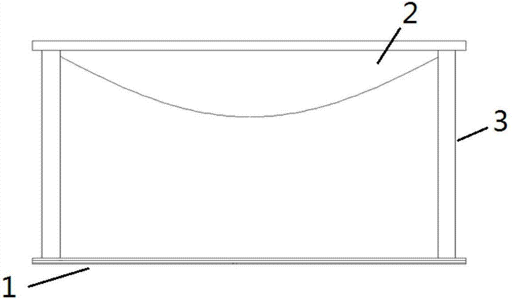
[0029] The circularly polarized microstrip antenna of the present invention is composed of a radiation unit 1 , a dielectric lens 2 and a support column 3 . Among them: the radiation unit 1 is composed of the parasitic patch layer 4 and the patch layer 5, the floor layer 6 and the feed network layer 7 are bonded to the lower part of the patch layer 5 in turn; the dielectric lens 2 is connected to the radiation unit 1 through four support columns 3 fixed together.

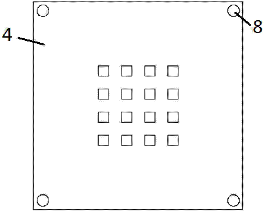
[0030] refer to figure 2 , the parasitic patch layer 4 is provided with a 4×4 metal patch array on its front, and upper through holes 8 are provided at the four corners, and the radius of the upper through holes 8 is about 2% to 5% of the side length of the radiation unit 1. %, take 2.5mm in this example.

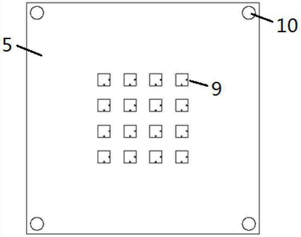
[0031] refer to image 3 , the patch layer 5 is provided with a 4×4 metal patch array on its front, and two sma...


PUM


Abstract

The invention discloses a circularly polarized microstrip antenna, and mainly solves the problems that an existing satellite high speed communication antenna is narrow in frequency band, low in gain, and large in size. The circularly polarized microstrip antenna comprises a radiating unit (1), a dielectric lens (2), a support pillar (3), a parasitic patch layer (4), a patch layer (5), a floor layer (6) and a feed network layer (7). The radiating unit (1) is formed by the parasitic patch layer (4) and the patch layer (5), the floor layer (6) and the feed network layer (7) are adhered on the lower portion of the patch layer (5) in sequence, an orthometric double-fed feed unit is arranged at the back face of the feed network layer (7), and the feed unit extends to the right edge of the feed network layer (7)through feeder lines, and is welded with a sub-miniature-A (SMA) coaxial interface to carry out feed. The dielectric lens (2) is fixed above the parasitic patch layer (4) through the support pillar (3). The circularly polarized microstrip antenna has the advantages of being high in gain, wide in frequency band, small in structure, and capable of being used in various mobile communication base stations.

Description

technical field [0001] The invention belongs to the field of microwave antennas, and relates to a circularly polarized microstrip antenna, which can be widely used in the fields of satellite high-speed communication and radar. Background technique [0002] With the rapid development of wireless communication technology, antenna technology involves more and more fields, and in many special applications, the requirements for antenna performance are also getting higher and higher. As an important part of the global information superhighway in the future, satellite communication has attracted more and more attention due to its characteristics of large coverage, no limitation of geographical environment, high reliability, and rapid circuit opening. In modern satellite high-speed communication, the antenna required to be used has the characteristics of high frequency, high gain, wide frequency band, circular polarization, and miniaturization. In order to meet the actual needs, st...

Claims


Application Information

Patent Timeline
Patent Type & Authority Applications(China)
IPC IPC(8): H01Q1/38H01Q1/50H01Q19/06
Inventor 雷振亚谢拥军杨锐侯建强满铭远樊君刘鑫
Owner XIDIAN UNIV
Why Eureka
Try Eureka