Cooling method and cooling device of end pump laser

A technology of cooling device and cooling method, which is applied in the field of end-pumped laser cooling, cooling device and laser source to achieve compact structure and good cooling effect.

Active Publication Date: 2013-07-10
INST OF SEMICONDUCTORS - CHINESE ACAD OF SCI
View PDF4 Cites 5 Cited by
  • Summary
  • Abstract
  • Description
  • Claims
  • Application Information

AI Technical Summary

Problems solved by technology

[0009] The technical problem to be solved by the present invention is to effectively cool the end-pumped laser with high injection power under the condition that water cooling cannot be used

Method used


Image

  • Cooling method and cooling device of end pump laser
  • Cooling method and cooling device of end pump laser
  • Cooling method and cooling device of end pump laser

Examples


Embodiment 1

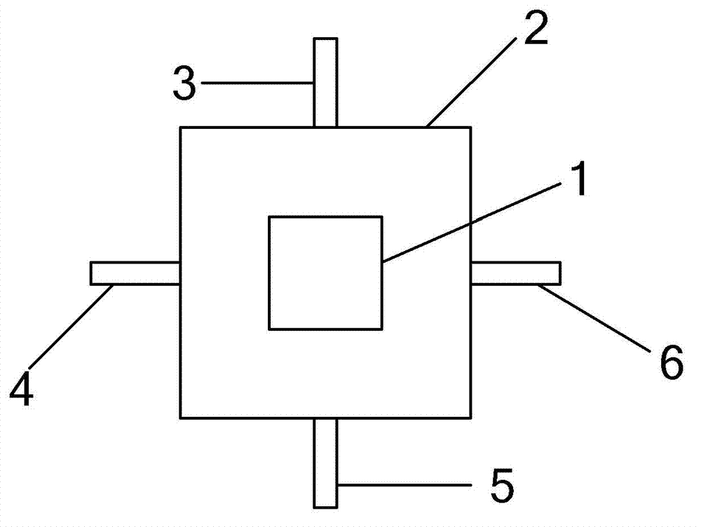
[0039] Embodiment 1 adopts end-pump pumping mode, as attached figure 1 2 is a square laser cavity that covers the crystal, and the pump light is focused inside the crystal after being focused. Laser crystals are placed in the cavity, of which 1 is a square laser crystal rod; in the vertical direction to the laser crystal rod, N slits are evenly opened on the laser cavity, and N rows of spray devices are arranged, of which 3, 4 , 5, 6 are 4 rows of spraying devices, wherein N=4; each row of spraying devices is provided with a spraying device every L1, wherein L1=11mm; the shortest distance between the spraying device and the laser crystal rod is L2, wherein L2=4mm; the flow rate of each spray device is P1, wherein P1=3.5mL / min; the diameter of the small water droplets produced by the spray is controlled at R2, wherein R2=110 μm; In the direction, there is an air inlet and an air outlet, and the blowing flow rate is P2, where P2=1.2L / min; the bottom of the cavity of the laser c...

Embodiment 2

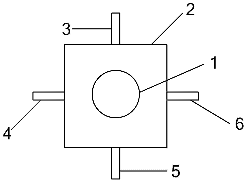
[0041] Embodiment 2 adopts end-pump pumping mode, as attached figure 2 2 is a square laser cavity that covers the crystal, and the pump light is focused inside the crystal after being focused. A laser crystal is placed in the cavity, 1 of which is a circular laser crystal; in the vertical direction to the laser crystal rod, N slits are evenly opened on the laser cavity, and N rows of spray devices are arranged, of which 3, 4 , 5, 6 are 4 rows of spraying devices, wherein N=4; each row of spraying devices is provided with a spraying device every L1, wherein L1=10mm; the shortest distance between the spraying device and the laser crystal rod is L2, wherein L2=4.5mm; The flow rate of each spray device is P1, wherein P1=3mL / min; the diameter of the small water droplets produced by the spray is controlled at R2, wherein R2=100 μm; In the direction, there is an air inlet and an air outlet, and the blowing flow rate is P2, where P2=1.35L / min; the bottom of the cavity of the laser c...

Embodiment 3

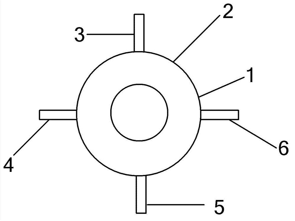
[0043] Embodiment 3 adopts end-pump pumping mode, as attached image 3 2 is a circular laser cavity covering the crystal, and the pump light is focused inside the crystal after being focused. A laser crystal is placed in the cavity, 1 of which is a circular laser crystal; in the vertical direction to the laser crystal rod, N slits are evenly opened on the laser cavity, and N rows of spray devices are arranged, of which 3, 4 , 5, 6 are 4 rows of spraying devices, wherein N=4; each row of spraying devices is provided with a spraying device every L1, wherein L1=10.5mm; the shortest distance between the spraying device and the laser crystal rod is L2, Wherein L2=3.5mm; The flow rate of each spray device is P1, wherein P1=3mL / min; the diameter of the small water droplets produced by the spray is controlled at R2, wherein R2=90 μm; parallel to the laser crystal rod In the direction of the air inlet and outlet, the blowing flow rate is P2, where P2 = 1.2L / min; the bottom of the cavi...


PUM


Abstract

The invention discloses a cooling method and a cooling device of an end pump laser. The end pump laser comprises a laser cavity and a laser crystal bar located in the laser cavity, a pumping mode of an end pump is adopted, and pumping lasers are focused inside the laser crystal bar. According to the cooling method of the end pump laser, a plurality of spraying devices are arranged on a cavity wall of the laser cavity, the spraying devices spray water mist to the laser crystal bar, an air inlet and an air outlet are arranged in the laser cavity and in the direction parallel with the laser crystal bar, and air flow in the laser cavity flows from the air inlet to the air outlet. The cooling method and the cooling device of the end pump laser are compact in structure, are good in cooling effect, and successfully resolve the problem that the end pump laser which can not be cooled with water can be cooled under the condition of high injection power.

Description

technical field [0001] The invention belongs to the technical field of solid-state lasers, and specifically relates to a cooling method and a cooling device for an end-pump laser, in particular to a cooling method that can be used to realize air-cooling under high injection power, so as to apply to inconvenient use of water cooling places, such as the laser source in the lidar system of a helicopter. Background technique [0002] Under the condition of high-power operation of solid-state lasers, the thermal effect generated by the temperature gradient distribution inside the gain medium occupies a dominant position in the distortion of the laser output mode, and the distortion generated by the thermal effect will lead to the instability of its output power and multiple modes. The coupling between them also limits the improvement of laser power, which seriously affects the performance of solid-state lasers. [0003] The main reasons for the thermal effect are: 1) The photon ...

Claims


Application Information

Patent Timeline
Patent Type & Authority Applications(China)
IPC IPC(8): H01S3/042
Inventor 赵伟芳林学春侯玮于海娟伊肖静李晋闽
Owner INST OF SEMICONDUCTORS - CHINESE ACAD OF SCI
Why Eureka
Try Eureka