
Semi-automatic plate-feeding machine

A board feeding machine and semi-automatic technology, applied in the direction of lamination device, object supply, pile separation, etc., can solve the problems of large investment in fixed assets, dislocation of surface layers, large installation area, etc., to improve the internal quality and appearance The effect of high quality, reduced production and operation costs, and small installation area

Inactive Publication Date: 2013-07-17
宜兴市一洲木业有限公司
View PDF3 Cites 2 Cited by
  • Summary
  • Abstract
  • Description
  • Claims
  • Application Information

AI Technical Summary

Problems solved by technology

[0002] The traditional hot-pressing production process of plywood for the bottom plate of the container basically has the following methods: one is to transport the pre-pressed and repaired slabs to the lifting table, and manually put them into the hot-pressing machine plate one by one. In the interior, it is required that the board-loading workers need to complete the entire board-mounting process within 120S. The proficiency of the board-mounting is high and the speed must be fast. The worker's operation process is complicated and consumes a lot of physical energy. Misalignment, seam separation, folding phenomenon
It will also occur that the board loading time exceeds the specified requirements, and the slab is in the hot press machine. Due to the high temperature of the hot plate, the adhesive layer is formed early and solidified, resulting in the surface peeling phenomenon, which seriously affects the internal quality and appearance of the plywood for the container floor. quality
The second is to adopt an automatic board feeding and discharging device, and a hot press is equipped with a set of automatic board feeding and discharging devices; the equipment installation occupies a large area, the investment in fixed assets is large, and the energy consumption and maintenance costs are large.

Method used


Image

  • Semi-automatic plate-feeding machine

Examples


Embodiment Construction

[0015] The present invention will be further described below in conjunction with accompanying drawing:

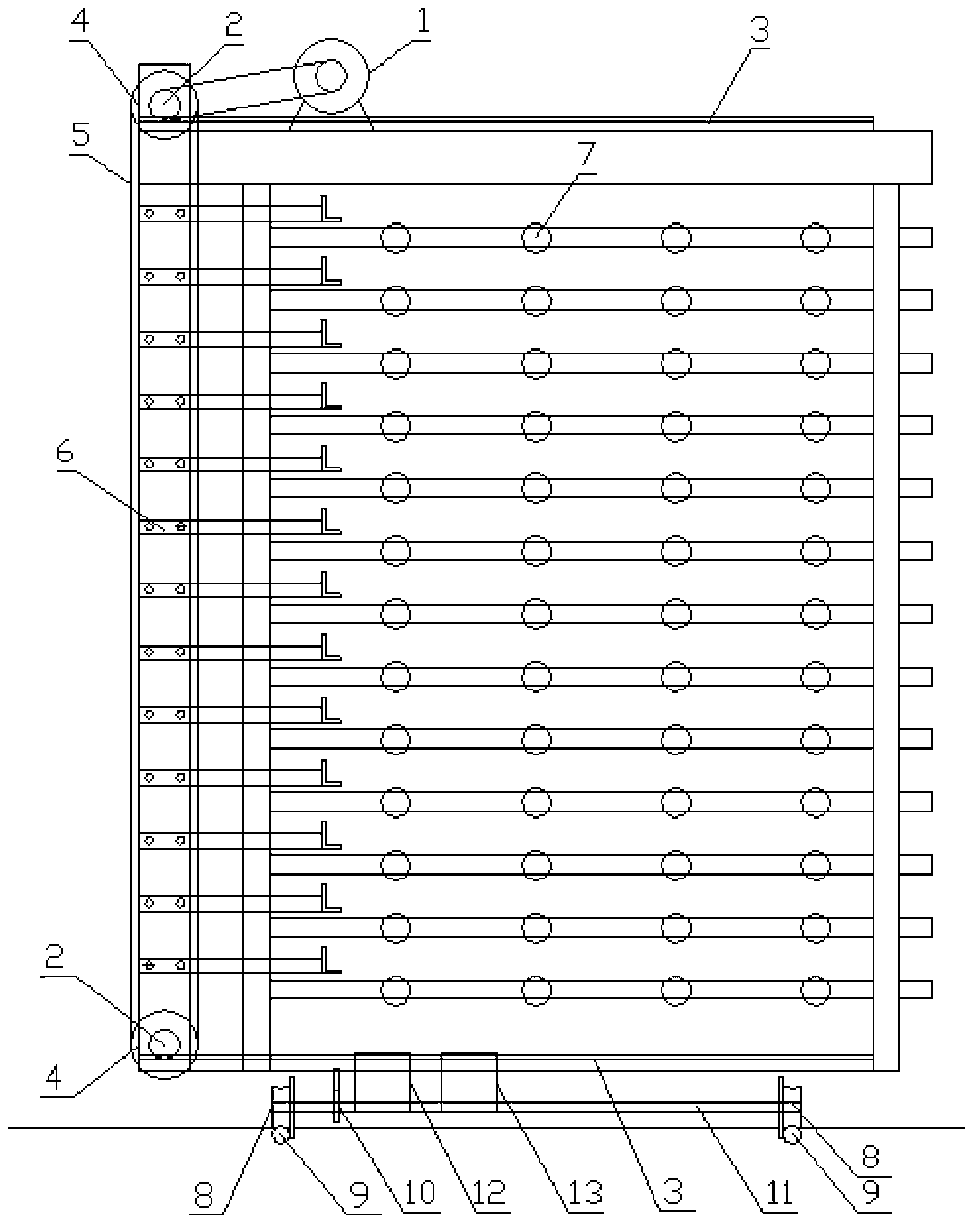
[0016] Such as figure 1 , the semi-automatic board feeder 4 includes the board feeder frequency conversion speed regulation motor 1, the transmission gear 2, the sprocket 4, the chain 5, the push board mechanism 6 and the roller 7, and the semi-automatic board feeder 4 is provided with multiple rows of rollers 7, each row of rollers The outer side of 7 is provided with a corresponding push plate mechanism 6, and a plurality of said push plate mechanisms 6 are arranged on the chain 5, and a sprocket 4 is respectively provided at the upper and lower ends of the chain 5, and the sprocket 4 is connected to the board frequency conversion through the transmission gear 2. Speed ​​motor 1.

[0017] The upper and lower sides of the semi-automatic plate feeder 4 are also provided with a tooth bar 3 connecting the transmission gear 2 .

[0018] The bottom of the semi-automatic plate...


PUM


Abstract

A semi-automatic plate-feeding machine is characterized by comprising a plate-feeding variable-frequency and variable-speed motor (1), transmission gears (2), chain wheels (4), a chain (5), plate pushing mechanisms (6) and rolling wheels (7). A plurality of rows of rolling wheels (7) are arranged in the semi-automatic plate-feeding machine, the corresponding plate pushing mechanisms (6) are arranged on the outer side of every row of rolling wheels (7), a plurality of plate pushing mechanisms (6) are arranged on the chain (5), the upper end and the lower end of the chain (5) are respectively provided with one chain wheel (4), and the chain wheels (4) are connected with the plate-feeding variable-frequency and variable-speed motor (1) through the transmission gears (2). By adopting the semi-automatic plate-feeding machine, labor intensity of operating workers and complexity in the operation process are reduced, easiness in malposition, joint opening, folding and face dropping and the like of a surface plate layer of plate blank are avoided, the semi-automatic plate-feeding machine is small in installing occupied space, less in investment and low in energy consumption and reduces production running cost.

Description

technical field [0001] The invention relates to a special semi-automatic feeding machine for hot-pressing production of plywood for container bottom boards. Background technique [0002] The traditional hot-pressing production process of plywood for the bottom plate of the container basically has the following methods: one is to transport the pre-pressed and repaired slabs to the lifting table, and manually put them into the hot-pressing machine plate one by one. In the interior, it is required that the board-loading workers need to complete the entire board-mounting process within 120S. The proficiency of the board-mounting is high and the speed must be fast. The worker's operation process is complicated and consumes a lot of physical energy. Misalignment, seam separation, folding phenomenon. It will also occur that the board loading time exceeds the specified requirements, and the slab is in the hot press machine. Due to the high temperature of the hot plate, the adhesive...

Claims


Application Information

Patent Timeline
IPC IPC(8): B65H5/24B32B37/10
CPCY02P70/10
Inventor 何学军
Owner 宜兴市一洲木业有限公司
Learn More