Finned spiral tube

A spiral tube and fin technology, applied in the field of new spiral tube devices, can solve the problems of unfavorable heat exchange efficiency of the fluid flow pattern in the tube, and achieve the effects of changing the flow pattern, enhancing the mass transfer effect, and increasing the degree of turbulence.

Active Publication Date: 2015-10-28
无锡苏惠信息技术服务有限公司
View PDF6 Cites 0 Cited by
  • Summary
  • Abstract
  • Description
  • Claims
  • Application Information

AI Technical Summary

Problems solved by technology

[0003] The present invention overcomes the shortcoming that the flow form of the fluid in the tube of the existing heat exchange spiral tube is not conducive to the heat exchange efficiency, and provides a finned spiral tube, which can make the gas-liquid two-phase flow in the spiral tube uniform distribution, and significantly improve the heat exchange efficiency of the fluid inside and outside the tube

Method used


Image

  • Finned spiral tube
  • Finned spiral tube
  • Finned spiral tube

Examples


Embodiment Construction

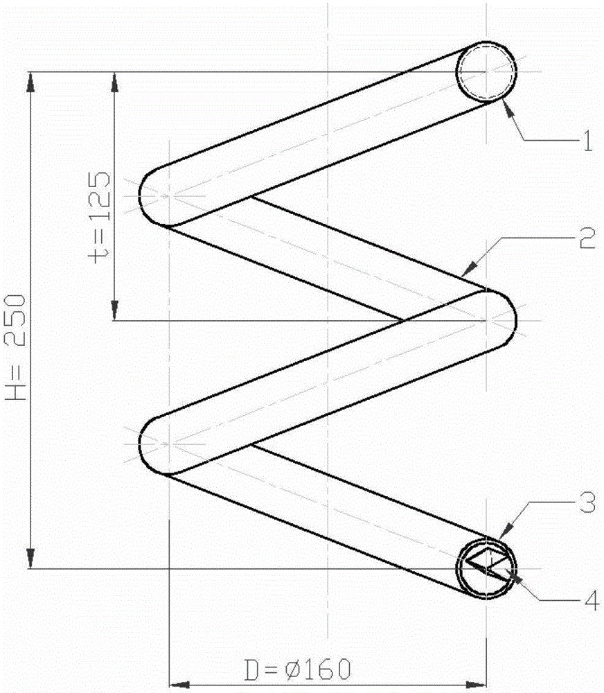
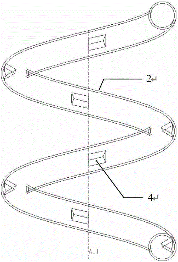
[0013] In the figure 1. Spiral tube outlet, 2. Spiral tube, 3. Spiral tube inlet, 4 fins.

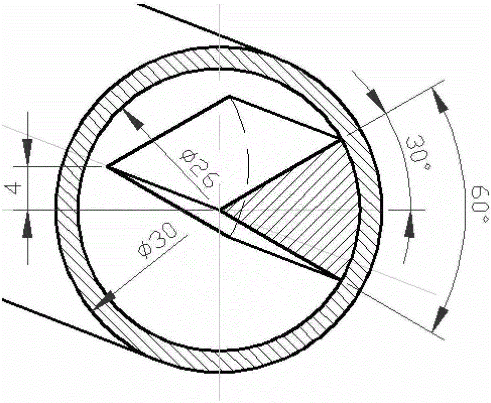
[0014] The finned spiral tube includes a spiral tube 2 with a circular section, and several fins 4 are evenly arranged on the inner wall of the spiral tube 2. For the convenience of processing and manufacturing, the fin 4 is a spiral structure with the same lead as the spiral tube 2; the fin 4 The cross-sectional shape of the fan is fan-shaped, and its radius is the same as that of the circular surface of the inner wall of the section of the spiral tube 2. The fins are arranged on the outer side of the inner wall of the spiral tube, and the center of the sector of the fin coincides with the center of the spiral tube.

[0015] exist figure 1 Among them, the invention is a helical tube with a pitch of t=125mm, the number of turns of the helical tube is n=2, the height of the helical tube is H=t×n=250mm, the helix of the helical tube is a cylindrical helix, and the diameter of the cylinde...


PUM


Abstract

The invention discloses a finned spiral pipe. The finned spiral pipe comprises a spiral pipe with a circular section, wherein a plurality of fins are evenly distributed on the inner wall of the spiral pipe, and the fins have the same spiral structure as that of the lead of the spiral pipe; the sections of the fins are shaped like a fan, and the radius of the section of each fin is equal to that of the circular surface of the inner wall of the section of the spiral pipe.

Description

Technical field [0001] The invention relates to a novel spiral tube device with fins, especially the spiral tube which can improve fluid flow form and enhance heat exchange efficiency. Background technique [0002] The spiral tube is a typical space curve tube. Because it can expand freely, it can effectively eliminate the temperature stress in the working process, and can greatly reduce the welding between the tube and the tube sheet. The leakage probability is small, the reliability is good, and the structure is compact. , high heat transfer efficiency, self-generated centrifugal force field and secondary flow, which can effectively delay the occurrence of heat transfer deterioration, so it is widely used in power, petroleum, chemical, navigation, aerospace and nuclear industries and other industries. For example, large-scale spiral tube heat exchange equipment in the petrochemical industry, separation equipment in extraction devices, rotor water cooling pipes for large do...

Claims


Application Information

Patent Timeline
Patent Type & Authority Patents(China)
IPC IPC(8): F28F1/40F28F13/12
Inventor 郑水华朱波牟介刚林玲施瀚昱范文粲
Owner 无锡苏惠信息技术服务有限公司
Why Eureka
Try Eureka