
Vertical load loading device for shear wall

A loading device and vertical loading technology, which is applied in the field of concrete construction, can solve the problem that the hydraulic jack cannot maintain the load value, etc., and achieve the effect of fewer instruments required for the test, simple assembly, and convenient operation

Inactive Publication Date: 2013-07-17
HOHAI UNIV +1
View PDF7 Cites 7 Cited by
  • Summary
  • Abstract
  • Description
  • Claims
  • Application Information

AI Technical Summary

Problems solved by technology

[0003] The invention aims at the problem that the hydraulic jack cannot maintain a fixed load value when the wall moves laterally under the horizontal load, and provides a vertical load loading device for the shear wall

Method used


Image

  • Vertical load loading device for shear wall
  • Vertical load loading device for shear wall
  • Vertical load loading device for shear wall

Examples


Embodiment Construction

[0015] The present invention will be described in further detail below in conjunction with the accompanying drawings and specific embodiments.

[0016] For the convenience of description, the "left", "right", "upper" and "lower" referred to below are consistent with the left, right, up and down directions of the drawings themselves, but do not limit the structure of the present invention.

[0017] Below in conjunction with accompanying drawing, the present invention is described in detail:

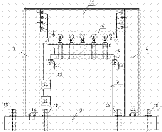
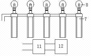
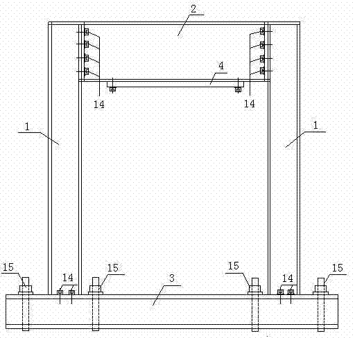
[0018] Such as figure 1 , 2 , 3, 4 shown. The bottom beam 3 is fixedly installed on the floor by ground anchor bolts 15, the two columns 1 are connected to the bottom beam 3 by high-strength bolts 14, and the reaction beam 2 is fixedly installed on the two columns by high-strength bolts 14. , the reaction beam 2 and the bottom beam 3 form a self-balancing reaction loading frame. The shear wall specimen 9 is placed on the bottom beam 3 . The bearing plate 5 is designed in an inverted U...


PUM


Abstract

The invention discloses a vertical load loading device for a shear wall. The vertical load loading device comprises a shear wall test piece, a polyfluortetraethylene plate, a bearing plate with concave holes on the top portion, more than five hydraulic jacks of the same specification, an antidumping net rack, pulleys and adjusting bolts which are in a counter-force system. The bearing plate with the concave holes on the top portion is arranged on the top portion of the shear wall test piece, the adjusting bolts are arranged on the left side and the right side of the bearing plate, the hydraulic jacks are arranged in the concave holes of the bearing plate and fixed through the antidumping net rack, the hydraulic jacks are connected in series through an oil pipe and connected with a hydraulic oil source and a pressure stabilizing system, the pulleys are arranged on the top portions of the hydraulic jacks, and the top portions of the pulleys are contacted with the polyfluortetraethylene plate at the bottom of a counter-force beam. The vertical load loading device is simple in structure, convenient to detach, suitable for exerting of vertical constant load during hysteresis performance testing of the shear wall test piece.

Description

technical field [0001] The invention relates to a vertical constant load loading device for a shear wall, which belongs to the field of concrete construction. Background technique [0002] In the field of civil engineering, the shear wall is the main anti-lateral component of the structure, and the study of its hysteretic performance is an important way to study the seismic performance of the structure. The axial compression ratio (the ratio of the vertical axial pressure of the shear wall to the product of the cross-sectional area and the concrete axial compressive strength) is generally fixed, that is, the vertical load is constant, and the vertical force is mainly loaded by a hydraulic jack , and the disadvantage of the existing device is that when the wall moves laterally under the action of vertical load, the hydraulic jack cannot maintain a fixed load value, and there is no anti-friction system between the hydraulic jack and the self-balancing reaction loading frame. ...

Claims


Application Information

Patent Timeline
Patent Type & Authority Applications(China)
IPC IPC(8): G01M99/00
Inventor 沈德建崔正华李明殷粉芳江倩艳邓树成
Owner HOHAI UNIV
Learn More