Piston for internal combustion engine

An internal combustion engine and piston technology, which is applied in the field of pistons used in internal combustion engines, can solve problems such as loss of function, and achieve the effects of prolonging service life and reducing loss.

Inactive Publication Date: 2013-07-17
MAHLE INT GMBH
View PDF8 Cites 0 Cited by
  • Summary
  • Abstract
  • Description
  • Claims
  • Application Information

AI Technical Summary

Problems solved by technology

[0003] However, this lubricant loses its effect after a certain period of time, since the ex...

Method used


Image

  • Piston for internal combustion engine
  • Piston for internal combustion engine
  • Piston for internal combustion engine

Examples


Embodiment Construction

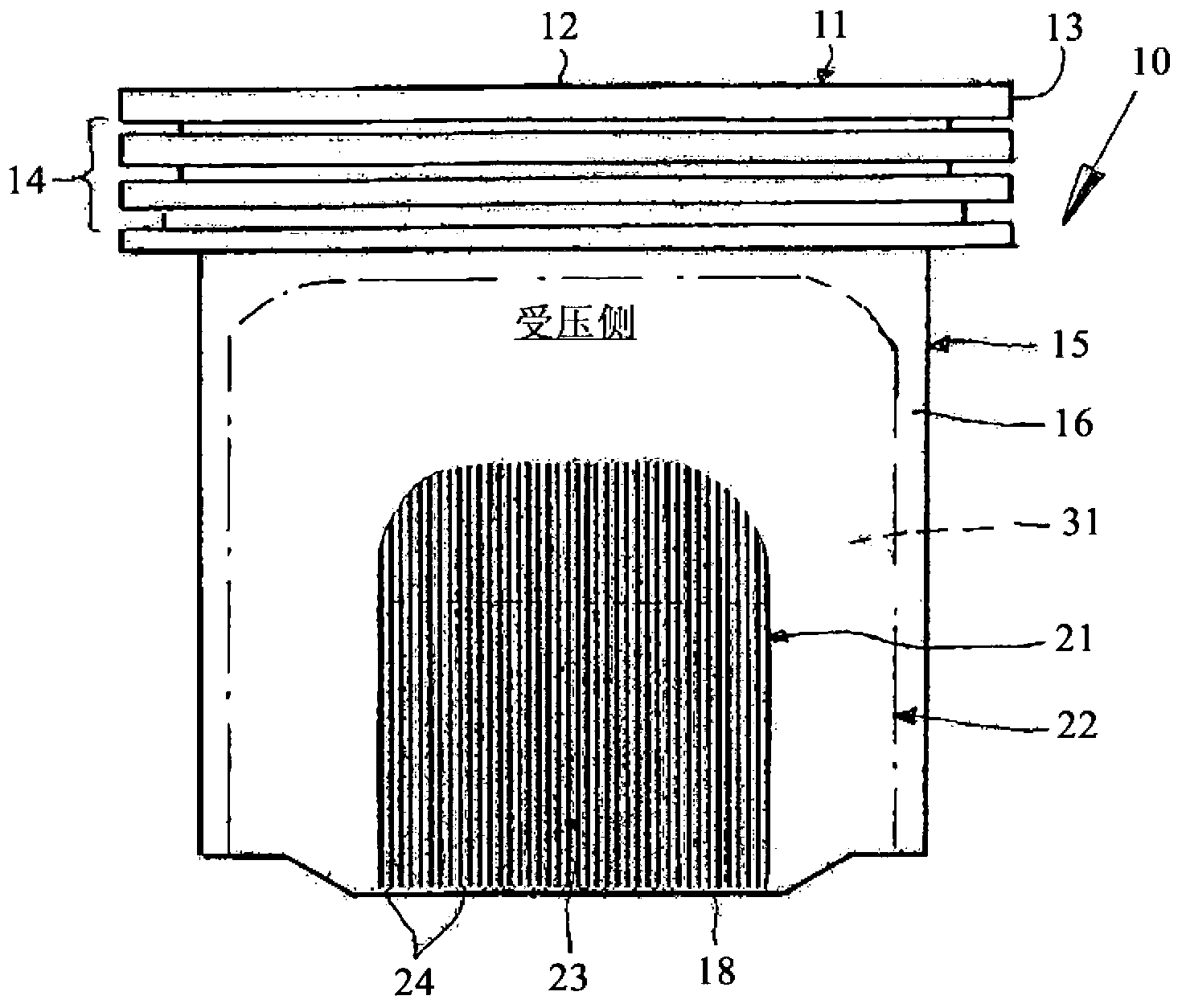
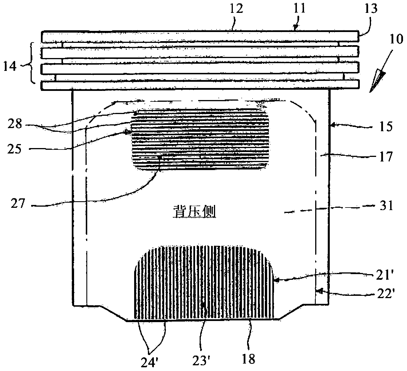
[0019] figure 1 and 2 An embodiment of a piston 10 according to the invention is shown. The piston 10 can be a one-piece or multi-part piston, for example a combined piston or a hinged piston. Piston 10 can be made of steel and / or light metal material. figure 1 and 2 A one-piece piston 10 is shown as an example. The piston 10 has a piston head 11 with a piston crown 12 ; a surrounding land 13 and an annular portion 14 for receiving piston rings (not shown). The piston 10 also has a piston skirt 15 with friction surfaces 16 , 17 . The piston skirt 15 is delimited by a lower skirt 18 . The friction surface 16 corresponds to the pressure side DS of the piston 10 (compare figure 1 ), while the friction surface 17 corresponds to the back pressure side GDS of the piston 10 (contrast figure 2 ). Other known structures of the piston skirt, such as hubs and hub bores, are not shown for clarity of illustration. The properties and load distribution of the pressure side and the...


PUM

PropertyMeasurementUnit
Widthaaaaaaaaaa

Abstract

The present invention relates to a piston (10) for an internal combustion engine, comprising a piston head (11) and a piston skirt (15) delimited by a lower skirt edge (18), wherein the piston skirt (15) comprises a running surface (16) associated with the pressure side (DS) of the piston skirt and a running surface (17) associated with the counter-pressure side (GDS) of the piston skirt and a zone (21, 21') is associated with each of the two running surfaces (16, 17), which zone starts from the lower skirt edge (18) and is exposed to a maximum load during the operation of the internal combustion engine. According to the invention, the zone (21) of the running surface (16) associated with the pressure side (DS) and/or the zone (21') of the running surface (17) associated with the counter-pressure side (GDS) is provided with a coating (23, 23') which has vertically extending grooves (24, 24').

Description

technical field [0001] The invention relates to a piston for an internal combustion engine, the piston having a piston head and a piston skirt defined by a lower skirt, wherein the piston skirt has a friction surface corresponding to its pressure side and a friction surface corresponding to its back pressure side, The two friction surfaces are each associated with a section which extends from the lower skirt and which is subjected to the greatest load during operation of the internal combustion engine. Background technique [0002] A generic piston is already known from DE 198 29 349 A1. Lubricant is applied to both the pressure side area and the back pressure side area of ​​the piston. This lubricates the areas of the friction surfaces of the piston that are particularly loaded due to lateral forces caused by the deflection of the connecting rod during operation. [0003] However, such lubricants lose their effectiveness after a certain period of time, since the existing ...

Claims


Application Information

Patent Timeline
IPC IPC(8): F02F3/10F16J1/08
CPCF05C2251/14F02F3/10F16J1/08
Inventor 罗尔夫-格哈德·菲德勒
Owner MAHLE INT GMBH
Why Eureka
Try Eureka