
Blood flow velocity imaging method based on transverse velocity model

An imaging method and flow velocity technology, applied in the field of blood flow imaging, can solve the problems of high cost and large influence of Doppler angle uncertainty, and achieve the effect of reducing requirements

Active Publication Date: 2013-07-24
蚌埠中知知识产权运营有限公司
View PDF6 Cites 4 Cited by
  • Summary
  • Abstract
  • Description
  • Claims
  • Application Information

AI Technical Summary

Problems solved by technology

However, this high-speed CMOS camera and the huge data transmission and processing speed required make the cost of this imaging technology very high, and the results of blood flow velocity are greatly affected by the uncertainty of Doppler angle.

Method used


Image

  • Blood flow velocity imaging method based on transverse velocity model
  • Blood flow velocity imaging method based on transverse velocity model
  • Blood flow velocity imaging method based on transverse velocity model

Examples


Embodiment Construction

[0024] The present invention is described in further detail by the following examples.

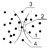
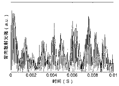
[0025] see Figure 4 As shown, a blood flow velocity imaging device based on a lateral flow velocity model is composed of a laser 10 , a beam expander 9 , an imaging system 8 , a CMOS camera 7 and a computer 11 . The object 6 to be measured is the blood flow on the surface of the palm, that is, the body surface. The laser beam emitted by the laser 10 is expanded by the beam expander 9 and irradiates the body surface 6. The expanded laser beam 5 and the body surface 6 are close to vertical. The imaging system 8 makes the irradiated The area is imaged by the CMOS camera 7, and the computer 11 controls the CMOS camera 7 to continuously collect images of the imaging area. Each pixel of the CMOS camera 7 acts as an independent detector to record the time-varying backscattered light intensity signal at the corresponding focal point. Assuming that the focal point corresponding to pixel 12 is 13, ...


PUM


Abstract

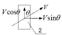
The invention provides a blood flow velocity imaging method based on a transverse velocity model. The method includes the steps that laser which is subjected to beam expansion is used for irradiating the body surface, and a CMOS camera is used for carrying out continuous imaging on irradiated areas; motion of red cells in shallow blood vessels of the body surface causes fluctuation of backscattering light intensity; an overall pixel matrix is used as a paralleled detector array, and each pixel in the CMOS camera is used as an independent detector; light intensity signals recorded by each pixel form an independent signal sequence, a normalized autocorrelation function of each signal sequence is calculated after continuous imaging; and the gradient of a linear area before a first zero point of the normalized autocorrelation function is the crossing time of the red cells transversely penetrating through detecting focal spots, and the transverse speed of the red cells is the transverse width of the detecting light focal spots.

Description

technical field [0001] The invention relates to the technical field of blood flow imaging, in particular to a blood flow velocity imaging method based on a transverse flow velocity model. Background technique [0002] Rapid imaging of blood flow velocity distribution in the superficial microcirculatory system of the body is widely used clinically. At present, non-invasive blood flow imaging techniques include: speckle technology, ultrasonic Doppler flow meter, laser Doppler Current meter, Doppler optical coherence tomography, laser Doppler blood flow imaging technology based on high-speed CMOS camera. Speckle technology cannot be used for quantitative measurement, nor is it suitable for faster flow rates. Ultrasonic Doppler flowmeter can only be used for large blood vessels and cannot be used for microcirculatory systems. Both Doppler optical coherence tomography and laser Doppler current meter are single-point measurements, which require mechanical scanning to achieve larg...

Claims


Application Information

Patent Timeline
Patent Type & Authority Applications(China)
IPC IPC(8): A61B5/0265
Inventor 王毅周红仙
Owner 蚌埠中知知识产权运营有限公司
Learn More