Sulphur condensing and separating deice of sulphur recovering device

A technology of sulfur recovery and separation equipment, which is applied in the direction of sulfur preparation/purification, which can solve problems such as soil pollution, air pollution, and damage, and achieve the effects of reducing environmental and soil pollution, reducing pollution, and reducing equipment investment

Active Publication Date: 2013-07-24
SHANDONG SUNWAY PETROCHEMICAL ENGINEERING CO LTD
View PDF3 Cites 3 Cited by
  • Summary
  • Abstract
  • Description
  • Claims
  • Application Information

AI Technical Summary

Problems solved by technology

Due to the short residence time of liquid sulfur in the condensing cooler, the dissolved amount of hydrogen sulfide is greater than the equilibrium dissolved amount in the cooling state, and the amount of hydrogen sulfide separated during the subsequent liquid sulfur degassing is relatively large. The current conventional liquid sulfur degassing process , most of them use air bubbling and liquid sulfur throwing for degassing, and the released gas is pumped to the incinerator together with nitrogen blanketing gas to form sulfur dioxide, which pollutes the atmosphere. The contribution of this part of pollutants to the sulfur dioxide emitted by the atmosphere is 100-300mg / m 3 , at the same time, because the liquid sulfur pool is operated under normal pressure, the hydrogen sulfide released from it will cause harm to the surrounding environment and related operators; while the sulfur sealing tank is set in the sulfur sealing tank pool below the ground, and the liquid sulfur pool is all located below the ground, so There is a risk of soil contamination from liquid sulfur

Method used


Image

  • Sulphur condensing and separating deice of sulphur recovering device

Examples


Embodiment 1

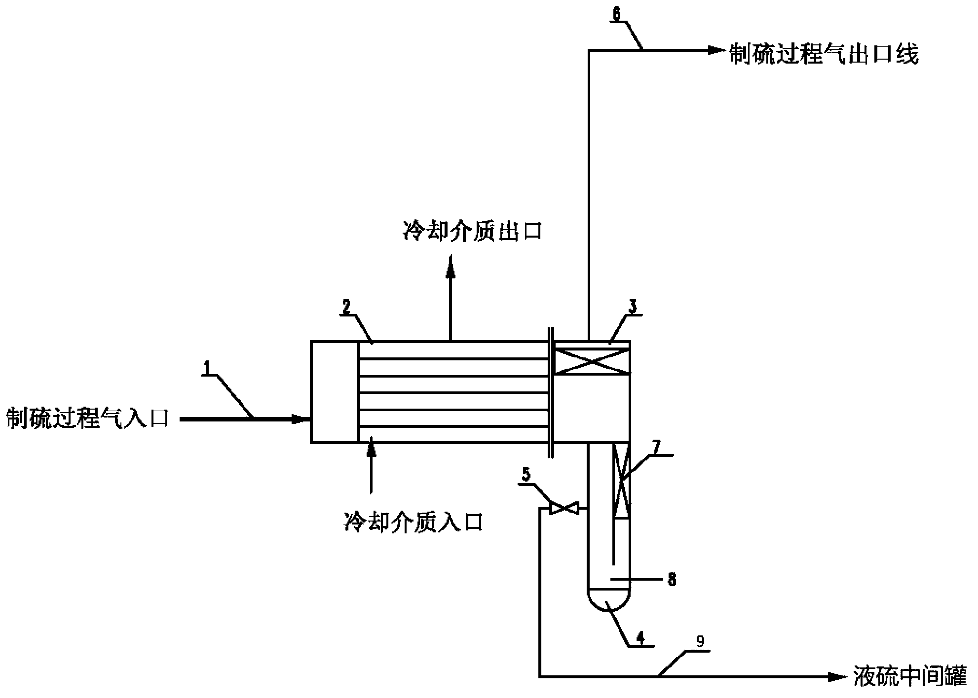
[0024] Such as figure 1 The sulfur condensation and separation equipment of the sulfur recovery unit shown includes a process gas condensation cooler 2 and a liquid sulfur separator 4. The liquid sulfur separator 4 is located below the head of the process gas condensation cooler 2. The head and liquid sulfur separator Steam heating facilities are arranged outside the sulfur separator 4. The liquid sulfur separator 4 is composed of a packing layer section 7 and a liquid sulfur collection section 8. The liquid sulfur separator 4 is provided with a liquid sulfur outlet, which is controlled by the liquid sulfur outlet valve 5. The sulfur outlet line 9 is connected to the liquid sulfur intermediate tank, and the liquid sulfur intermediate tank is connected to the liquid sulfur storage tank; the process gas outlet is provided with a liquid sulfur trap 3, and the process gas outlet is connected to the sulfur production process gas outlet line 6, and the sulfur production process gas o...

Embodiment 2

[0028] Such as figure 1 The sulfur condensation and separation equipment of the sulfur recovery unit shown includes a process gas condensation cooler 2 and a liquid sulfur separator 4. The liquid sulfur separator 4 is located below the head 2 of the process gas condensation cooler. The head and liquid sulfur Steam heating facilities are arranged outside the separator 4. The liquid sulfur separator 4 is composed of a packing layer section 7 and a liquid sulfur collection section 8. The liquid sulfur separator 4 is provided with a liquid sulfur outlet, which is controlled by the liquid sulfur outlet valve 5. The outlet line 9 is connected to the liquid sulfur intermediate tank, and the liquid sulfur intermediate tank is connected to the liquid sulfur storage tank; the process gas outlet is provided with a liquid sulfur trap 3, the process gas outlet is connected to the sulfur production process gas outlet line 6, and the sulfur production process gas outlet line 6 is connected to...


PUM


Abstract

The invention relates to a combined device for condensing and separating sulphur of a sulphur recovering device. The combined device is combined by a process gas condensing cooler and a liquid sulphur separator. The liquid sulphur separator is directly connected below the end socket of the process gas condensing cooler and forms an integral space together with the end socket. A steam heating facility is arranged outside the end socket of the process gas condensing cooler and the liquid sulphur separator. The liquid sulphur separator is internally provided with a filler layer section and a liquid sulphur collecting section. The filler layer is in a normal filler structure. A process gas outlet is provided with a liquid sulphur capturer and is connected with a next stage reaction or condensing cooling system. The liquid sulphur separator is provided with a liquid sulphur outlet valve which controls the liquid sulphur to flow out. The liquid sulphur outlet valve is connected to a liquid sulphur middle tank through a liquid sulphur outlet line. According to the combined device provided by the invention, the investment on devices is reduced and the environment and a human body are not damaged, the content of hydrogen sulfide entrained by liquid sulphur treated is low, and the content of sulphur dioxide in exhaust gas is low, so that the environmental pollution is reduced.

Description

technical field [0001] The invention belongs to the technical field of sulfur recovery, and in particular relates to a sulfur condensation and separation combination equipment and process suitable for a sulfur recovery device. Background technique [0002] In the existing sulfur recovery device, the liquid sulfur condensed by the process gas condensing cooler is directly sent from the condensing cooler to the sulfur sealing tank installed below the ground, and then the gravity of the liquid sulfur is used to flow into the normal pressure liquid sulfur pool. Due to the short residence time of liquid sulfur in the condensing cooler, the dissolved amount of hydrogen sulfide is greater than the equilibrium dissolved amount in the cooling state, and the amount of hydrogen sulfide separated during the subsequent liquid sulfur degassing is relatively large. The current conventional liquid sulfur degassing process , most of them use air bubbling and liquid sulfur throwing for degass...

Claims


Application Information

Patent Timeline
Patent Type & Authority Applications(China)
IPC IPC(8): C01B17/05
Inventor 刘桂玲
Owner SHANDONG SUNWAY PETROCHEMICAL ENGINEERING CO LTD
Why Eureka
Try Eureka