Method for on-line monitoring and alarming of convection heating face flue gas temperature field of power station boiler

A technology for flue gas temperature and power station boilers, which is used in the indication of boiler working conditions, lighting and heating equipment, control systems, etc. Boiler operating pressure and temperature increase, to achieve the effect of extending service life, ensuring safe and economical operation, and eliminating pipe bursts

Active Publication Date: 2013-07-24
王衡 +1
View PDF9 Cites 23 Cited by
  • Summary
  • Abstract
  • Description
  • Claims
  • Application Information

AI Technical Summary

Problems solved by technology

[0007] The shortcomings of this technology are: (1) Intelligent wall temperature management is only performed on the two tube groups of the final stage superheater and the final reheater of the power plant boiler, and does not manage the temperature of the primary superheater, secondary superheater, and tertiary superheater. , four-stage superheater and low and high temperature reheaters for wall temperature management
(2) There is no display and monitoring of the smoke temperature distribution at the inlet and outlet of the monitoring tube group
[0009] The disadvantage of this technology is that only the unevenness of the flue gas heat release intensity along the furnace width direction of the monitoring tube group is monitored, and there is no display and monitoring of the smoke temperature distribution at the inlet and outlet of the monitoring tube group.
[0011] The disadvantage of this technology is: the patent only calculates the smoke temperature, smoke velocity and tube wall temperature of the boiler panel superheater, and does not display and monitor the smoke temperature of the high temperature superheater and high temperature reheater
[0013] The disadvantage of this technology is: the patent does not calculate and monitor the flue gas temperature of the superheater reheater pipe system of the power plant boiler
[0015] The disadvantage of this technology is: the patent only measures the components of the flue gas on the water wall, and does not measure and monitor the temperature distribution of the flue gas on the water wall and the superheater reheater piping system (convection heating surface)
[0017] The disadvantage of this technology is: the patent does not calculate and monitor the flue gas temperature of the superheater reheater pipe system of the power plant boiler
[0018] The boiler tube explosion accident will not only cause tens of millions of direct economic losses, but also greatly reduce the life of the tube group, and the large temperature deviation cannot be eliminated in time, and there is also a hidden danger of continuous tube explosion; at the same time, the current situation in our country is supercritical A large number of ultra-supercritical generators and ultra-supercritical generators have been put into operation, and the operating pressure and temperature of boilers have increased significantly. The application of boiler metal materials has approached the highest temperature-resistant grade. There are obvious limitations in the development and progress of existing technologies in the past ten years. In terms of detection methods It still seems relatively extensive, especially reflected in the accuracy of online actual measurement and the processing of boiler temperature field detection data, so as to directly and timely adjust the combustion working conditions online and give full play to the real-time and accurate monitoring function of the inner wall temperature of the high-temperature tube system. It has very important guiding significance for reducing temperature deviation, prolonging the service life of high-temperature tube panels and adjusting the combustion of boilers. Its economic benefits, energy-saving and emission reduction indicators are very prominent, and it is closely and urgently related to the national energy construction in China's 12.5 plan.

Method used


Image

  • Method for on-line monitoring and alarming of convection heating face flue gas temperature field of power station boiler

Examples


Embodiment 1

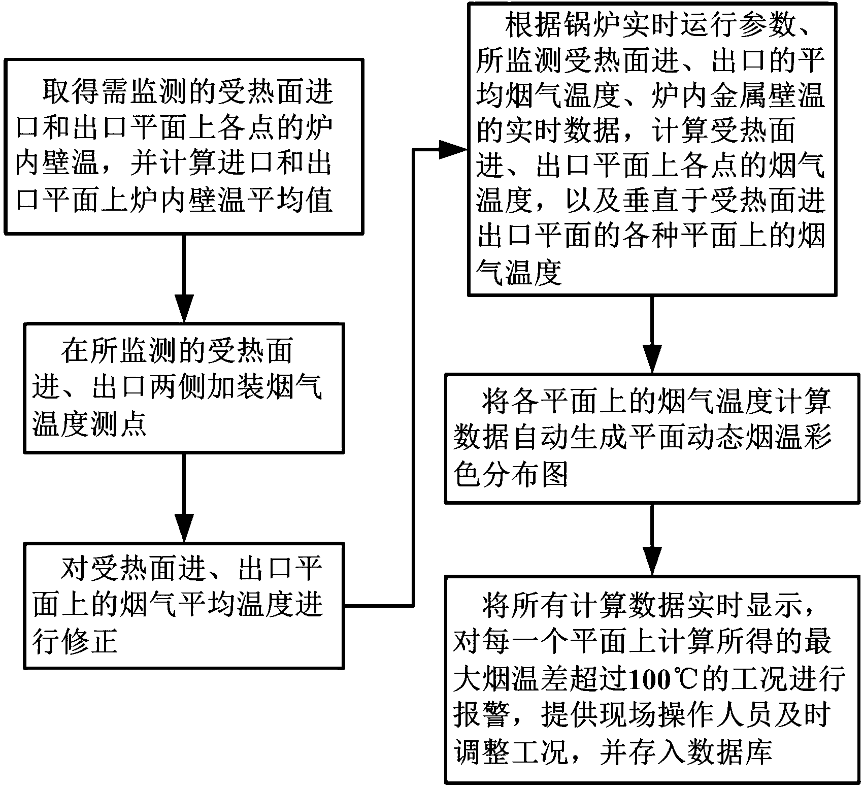
[0070] In this embodiment, the inlet plane of the final superheater of a 1036MW ultra-supercritical boiler in a power plant is selected as an embodiment. use figure 1 The block schematic diagram of the implementation steps is shown.

[0071] This embodiment includes the following steps:

[0072] Step 1: According to the monitoring of the dynamic metal wall temperature in the convection heating surface furnace of the utility boiler, obtain the monitoring values ​​of the furnace inner wall temperature at each point on the inlet and outlet planes of the heating surface, and calculate the average value of the furnace inner wall temperature on the inlet and outlet planes;

[0073] This embodiment calculates the import through the existing technology (Chinese patent document number: CN102494325A, publication date: 2012-06-13, named: method for monitoring dynamic wall temperature in the high-temperature tube system of power plant boiler, etc.) The average temperature of the inner wal...


PUM


Abstract

The invention belongs to a method for the on-line monitoring and alarming of a convection heating face flue gas temperature field of a power station boiler, which comprises the steps of calculating the average value of temperatures of furnace inner walls on inlet and outlet planes according to monitoring values of the temperatures of the furnace inner walls; additionally arranging flue gas temperature monitoring points at two sides; amending a flue gas average temperature; calculating the flue gas temperature of each point in the inlet and outlet planes of the heating faces, and the flue gas temperature of various planes vertical to the inlet and outlet planes of the heating faces; automatically generating a planar dynamic flue gas temperature colorful distribution diagram; and displaying in real time and providing site conditions and timely adjusting work conditions. The method disclosed by the invention realizes the accurate data monitoring and corresponding and visual diagram distribution display of flue gas temperature fields in the inlet and outlet planes and various longitudinal and horizontal planes vertical to the inlet and outlet planes of each convection heating face of superheater and reheater pipeline systems, provides direct data support for adjusting the burning work condition of the operation site of the power station boiler, and realizes the safe and economic operation of the convection heating faces of the superheater and reheater pipeline systems of the power station boiler.

Description

technical field [0001] The invention relates to a combustion optimization operation method in the technical field of boilers, in particular to a method for on-line monitoring and warning of flue gas temperature field on a convection heating surface of a utility boiler. Background technique [0002] When global warming and the greenhouse effect seriously threaten the survival of human beings, governments and scientific and technological personnel of various countries pay great attention to the energy consumption of thermal power generation and its safe operation, and take active measures to control it, especially in the high-speed power plant boilers in our country. In the development, accidents such as material overheating and scale formation in the tubes occur frequently and fall off and block the tubes. Therefore, delaying the formation of scales in the tubes and prolonging the service life of the piping system have become urgent technical problems to be solved for power pl...

Claims


Application Information

Patent Timeline
IPC IPC(8): F22B35/18F22B37/38
Inventor 王衡王孟浩
Owner 王衡
Why Eureka
Try Eureka