Porous screw blade rotor in heat exchange tube

A technology of helical blades and heat exchange tubes, applied in the field of porous helical blade rotors, can solve the problems of insignificant effect of field synergy to strengthen heat transfer, damage to the inner wall of heat exchange tubes, and short service life of bearings, saving materials and enhancing the effect of mixed flow. , the effect of reducing the operating speed

Inactive Publication Date: 2013-07-24
BEIJING UNIV OF CHEM TECH
View PDF6 Cites 19 Cited by
  • Summary
  • Abstract
  • Description
  • Claims
  • Application Information

AI Technical Summary

Problems solved by technology

As a typical tube-side enhanced heat transfer method, the insert has attracted widespread attention. One of them is to use the fluid to drive the spiral bond to rotate to realize the method of strengthening online automatic descaling. The Chinese patent application number of the spiral bond is: ZL95236063.2, the patent name is the invention of "cleaning device for descaling and anti-scaling in heat transfer tube". This device plays a certain role in strengthening heat exchange and anti-scaling and descaling. The bond is a whole, which directly scratches the heat transfer tube and damages the inner wall of the heat exchange tube; (2) When the fluid flows to push the bond to rotate, a large driving torque is required, which consumes more fluid kinetic energy; (3) Single-ended fixing The service life of the bearing is short; (4) The field synergy enhanced heat transfer effect generated by the bond is not significant
But the disadvantage is that the rotor will be unbalanced or eccentric when it rotates under the action of the fluid, which will cause the top of the blade to scratch against the inner wall of the heat exchange tube, reducing its service life. In addition, due to the intermittent impact of the fluid on the front end of the blade, a certain amount of fluid resistance will be generated.

Method used


Image

  • Porous screw blade rotor in heat exchange tube
  • Porous screw blade rotor in heat exchange tube
  • Porous screw blade rotor in heat exchange tube

Examples


Embodiment Construction

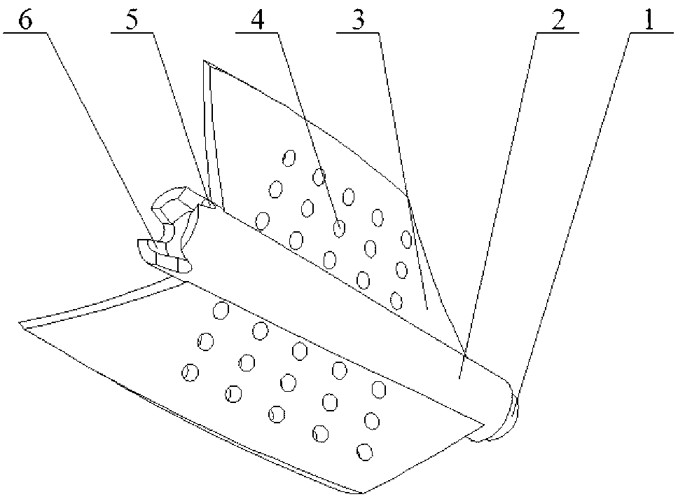
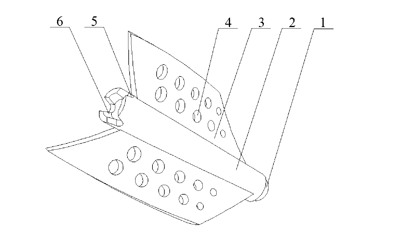
[0019] Such as Figure 5 As shown, the present invention is a porous helical blade rotor in a heat exchange tube. The enhanced heat transfer device includes a rotor, a rotating shaft 7, a heat exchange tube 8 and a hanging piece 9. Several rotors are connected in series through the rotating shaft 7. The hanging piece 9 is fixed on the heat exchange tube. The two ends of the tube 8 and the two ends of the rotating shaft 7 are respectively fixed on the pendant 9. The rotor of the present invention is composed of a certain number of porous spiral blades 3 fixed on the surface of the hollow shaft 2, and the hollow shaft 2 is also provided with a ball-and-socket protrusion Table 1, a hole 5 communicating with the inner hole of the hollow shaft and a ball-and-socket concave table 6. Among the two adjacent rotors, the ball-socket boss 1 at the head of the hollow shaft 2 of one rotor is combined with the ball-socket recess 6 at the tail of the other rotor to connect and adjust them to...


PUM


Abstract

The invention relates to a porous screw blade rotor in a heat exchange tube. The porous screw blade rotor is formed by a hollow shaft and porous screw blades. The porous screw blades are evenly distributed on the surface of the hollow shaft. The external diameter of the porous blades is smaller than the internal diameter of the heat exchange tube. The blades are in a spiral shape around the hollow shaft, and micropore structures are arranged on the surfaces of the blades along the axial direction and the radial direction of the hollow shaft. Micropores keep a certain distance from the hollow shaft. Edges, being firstly contacted with water flow, of micropore blades form slant chamfers or round chamfers. Holes communicated with inner holes of the hollow shaft are evenly formed in the hollow shaft far from a water inlet end along the circumferential direction. The rotary torque of fluid to the rotor and a combination fixing mode of the porous blades on the hollow shaft can be changed through changing of spiral angles of the porous screw blades along the axial direction of the hollow shaft, the axial length of the hollow shaft, the height along the radial direction of the hollow shaft, the distance between the micropores and root portions of the blades, sizes of the micropores, spaces between the micropores, the arrangement mode of the micropores and the number of the micropores along the axial direction and the radial direction of the hollow shaft so as to facilitate installation of the rotor in the heat exchange tube.

Description

technical field [0001] The invention relates to an insert device applied to the energy-saving technology of shell-and-tube heat exchangers, in particular to a porous spiral blade with enhanced heat transfer and self-cleaning functions, which is suitable for fluid containing gas phase, has low resistance and long service life rotor. Background technique [0002] Many heat exchangers are used in many fields such as petroleum, chemical industry, thermal power, nuclear power, metallurgy, light industry, aviation equipment and ship vehicles, among which the shell and tube heat exchanger is the most widely used, but in these heat exchangers There is generally layered dirt on the inner wall of the tube, which increases the resistance of fluid transport in the pipeline, and in severe cases will block the pipeline, and at the same time the heat transfer performance will be greatly reduced; the dirt in the heat exchange tube will seriously reduce the heat transfer efficiency and cause...

Claims


Application Information

Patent Timeline
Patent Type & Authority Applications(China)
IPC IPC(8): F28F13/12F28G3/00
Inventor 杨卫民张震阎华关昌峰蒋晨丁玉梅
Owner BEIJING UNIV OF CHEM TECH
Why Eureka
Try Eureka