Rotational inertia on-line identification method for alternating current (AC) permanent magnet synchronous motor servo system

A permanent magnet synchronous motor, rotational inertia technology, applied in control systems, control generators, vector control systems, etc., can solve the problem of high requirements for digital processing chip storage space and operation speed

Active Publication Date: 2013-07-24
HARBIN INST OF TECH
View PDF5 Cites 34 Cited by
  • Summary
  • Abstract
  • Description
  • Claims
  • Application Information

AI Technical Summary

Problems solved by technology

[0004] The present invention is to solve the problem that the online inertia identification method based on the traditional least squares method has high requirements on the storage space and operation speed of the digital processing chip, and provides an online identification method for the rotational inertia of the AC permanent magnet synchronous motor servo system

Method used


Image

  • Rotational inertia on-line identification method for alternating current (AC) permanent magnet synchronous motor servo system
  • Rotational inertia on-line identification method for alternating current (AC) permanent magnet synchronous motor servo system
  • Rotational inertia on-line identification method for alternating current (AC) permanent magnet synchronous motor servo system

Examples


specific Embodiment approach 1

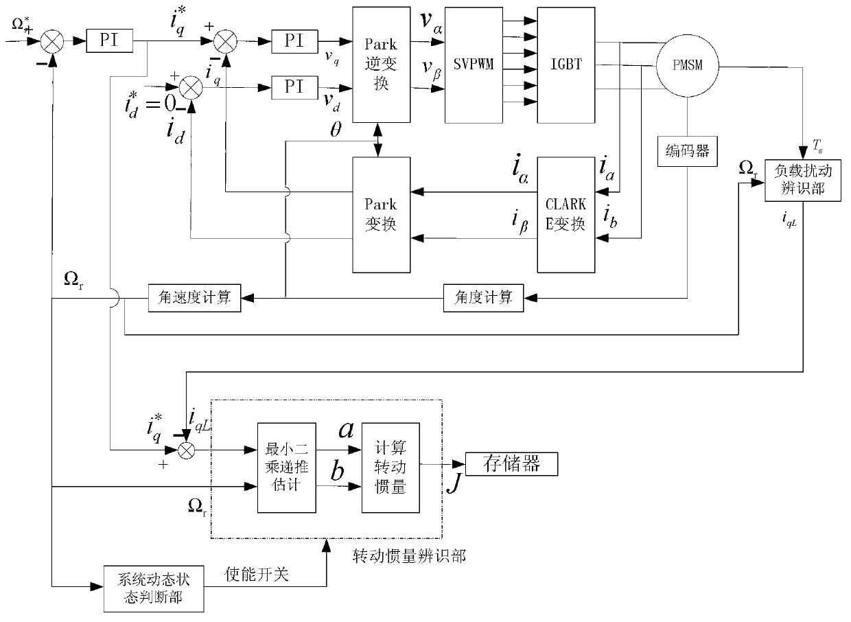
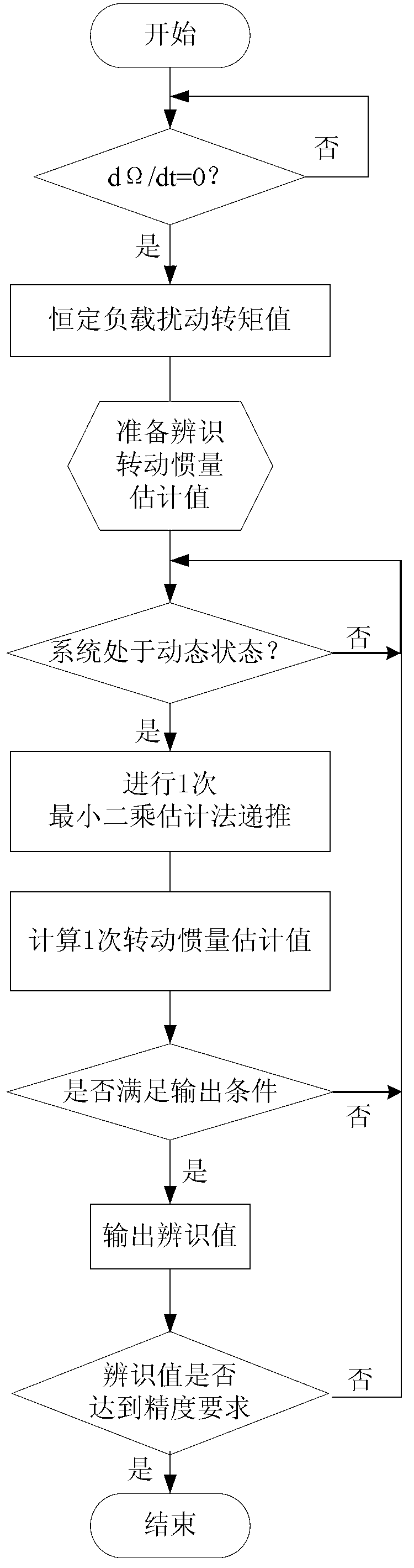
[0050] Specific implementation mode one: the following combination figure 1 with figure 2 Describe the present embodiment, the online identification method of the moment of inertia of the AC permanent magnet synchronous motor servo system described in the present embodiment, the online identification method is used in the dynamic operation process of the motor, and it is characterized in that it includes the following steps:

[0051] Step 1: Use the load torque identification unit to identify the constant load disturbance torque value T L ;

[0052] Step 2: Use the system dynamic state judgment part to judge whether the motor speed is in a dynamic change stage. When the motor speed is in a dynamic change stage, and the change rate of the motor speed is higher than the critical change rate of the motor moment of inertia identification, use the recursive based The estimated value of the moment of inertia is obtained by calculating the least square estimation method;

[0053]...

specific Embodiment approach 2

[0058] Specific Embodiment 2: This embodiment further explains Embodiment 1. In Step 1 of this embodiment, the load torque identification unit is used to identify the constant load disturbance torque value T L The specific method is:

[0059] According to constant load disturbance torque T L The mechanical equation of motion:

[0060] J dΩ r dt + BΩ r + T L = T e ,

[0061] In the formula, J is the estimated value of the moment of inertia to be identified, Ω r is the mechanical angular velocity of the motor rotor, t is time, B is the viscous friction coefficient, T e is the electromagnetic torque of the motor;

[0062] when when T e = BΩ r +T L , ignore BΩ at this time r , with T e ≈T L , thus identifying the constant load disturbance torque ...

specific Embodiment approach 3

[0067] Specific implementation mode three: the following combination Figure 1 to Figure 6 Describe this embodiment, this embodiment will further explain Embodiment 2, the specific method for calculating and obtaining the estimated value of moment of inertia J by using the least squares estimation method based on recursion described in this embodiment is:

[0068] With a given q-axis component i of the stator current q To overcome the constant load disturbance torque T L The stator current q-axis component i qL The difference is used as input, and the mechanical angular velocity of the motor rotor Ω r As output, the transfer function H(s) of the motor dynamics in Laplace form is obtained:

[0069] H ( s ) = Ω r ( s ) ΔI q ...


PUM


Abstract

The invention relates to a rotational inertia on-line identification method for an alternating current (AC) permanent magnet synchronous motor servo system and belongs to the technical field of rotational inertia identification for motors. The method aims to solve the problems that an on-line inertia identification method based on the traditional least square method is high in requirements for storage space and arithmetic speed of digital processing chips. The method adopts a load torque identification part to identify a constant load disturbance torque value TL; a system dynamic state judging part is adopted for judging whether rotation speed of a motor is at a dynamic change stage, and when the rotation speed of the motor is at the dynamic change stage and the rate of change of the rotation speed of the motor is higher than a critical change rate for identification of rotational inertia of the motor, a rotational inertia estimation value is obtained through calculation by utilization of a least square estimation method based on recursion; and when the rotational inertia on-line identification process meets requirements of a preset output rotational inertia estimation value and meets a requirement for precision, the rotational inertia estimation value is output and the rotational inertia on-line identification process is completed. The method is used for rotational inertia on-line identification for the motor servo system.

Description

technical field [0001] The invention relates to an online identification method for moment of inertia of an AC permanent magnet synchronous motor servo system, and belongs to the technical field of moment of inertia identification for electric motors. Background technique [0002] The servo system of the motor needs to have very good dynamic characteristics and the robustness of specific performance indicators. Appropriate controller parameters will bring a good dynamic response, and the controller parameters need to be combined with the inherent properties of the servo motor itself to configure relatively better parameter values. Since the moment of inertia of the motor and load is related to the configuration of the controller parameters, the servo control system should have the ability to detect the change of the load torque at any time and accurately identify the equivalent moment of inertia of the motor and load, so as to better realize the controller PI Parameter auto...

Claims


Application Information

Patent Timeline
Patent Type & Authority Applications(China)
IPC IPC(8): H02P21/14
Inventor 杨明刘子剑徐殿国
Owner HARBIN INST OF TECH
Why Eureka
Try Eureka