Common mode filter based on C type coupling defected ground structure

A technology of common-mode filter and defective ground structure, which is applied in the fields of high-speed circuits, electromagnetic fields and microwaves. It can solve the problems of increased design difficulty, increased bandwidth, and too many design parameters, and achieves fewer structural parameters and smaller effective electrical dimensions. , The effect of simple structure design

Inactive Publication Date: 2013-07-24
NANJING UNIV OF SCI & TECH
View PDF2 Cites 12 Cited by
  • Summary
  • Abstract
  • Description
  • Claims
  • Application Information

AI Technical Summary

Problems solved by technology

Comparing the two defect structures, the coupled HU-type defect structure can reduce the electrical size of the common-mode filter and increase the bandwidth, but due to too many design parameters, the design difficulty increases

Method used


Image

  • Common mode filter based on C type coupling defected ground structure
  • Common mode filter based on C type coupling defected ground structure

Examples


Embodiment

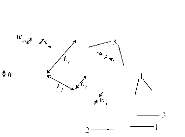
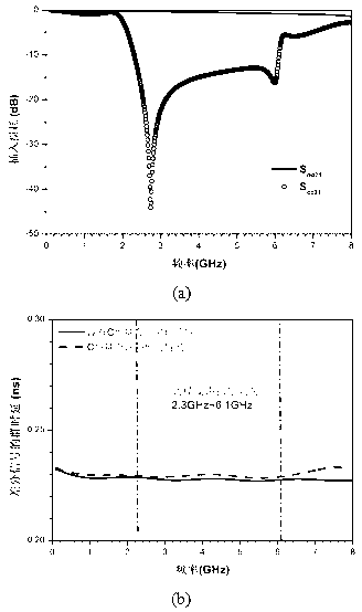
[0014] Example: Combine figure 1 and figure 2 The common mode filter of the C-type coupling defect ground structure suppresses the stopband frequency range of 2.3GHz-6.1GHz with common mode noise -10dB (the differential signal group delay is in the common mode noise before and after the introduction of the C-type coupling defect ground structure Suppression stop band is basically unchanged) as an example, the specific implementation of the structure of the present invention will be described in detail.

[0015] According to the following parameters, etch two C-shaped grooves 5 with opposite opening directions on the basis of all copper-covered ground layer 1 of the 2-layer printed circuit board, and the groove width of the C-shaped groove w s =1mm, slot arm such as figure 1 Shown are L 1 =10mm, L 2 =6mm, L 3 =4mm, the distance between two C-shaped grooves g =0.5mm. The coupled microstrip line 4 is printed on the wiring layer 3 on the top layer of the circuit board,...


PUM


Abstract

The invention discloses a common mode filter based on a C type coupling defected ground structure. A coupled microstrip line used for transferring high-speed differential signals is manufactured on the top surface of a double-layer printed circuit board. The bottom surface of the circuit board is coated with copper to be used as a ground player. Two C type grooves are symmetrically etched on a ground plane right under the coupled microstrip line; namely, the grooves are of a defected ground structure. Directions of openings of the two C type grooves are opposite. The common mode filter based on the C type coupling defected ground structure is simple in design, few in structure parameters and small in effective electricity size.

Description

technical field [0001] The invention belongs to the technical fields of high-speed circuits, electromagnetic fields and microwaves, and specifically relates to a common-mode filter based on a C-type coupling defect ground structure, which can be used to suppress common-mode noise in the GHz frequency band on a differential line of a high-speed circuit. Background technique [0002] As high-speed electronic systems increase the reliability of data transmission, differential signals play an increasingly important role. The main reason is that differential signals are not sensitive to external noise, have low crosstalk, and low electromagnetic radiation. For example: Many high-speed serial link standards (PCI-Express 2.0, USB 3.0, SATA III, etc.) have achieved differential signal transmission exceeding 5Gbps. However, due to the jitter of the differential signal in the actual circuit, the inconsistency of the rising / falling edge of the differential signal, and the limitation of...

Claims


Application Information

Patent Timeline
Patent Type & Authority Applications(China)
IPC IPC(8): H03H7/01H03H1/00
Inventor 唐万春陈如山施永荣刘升王橙饶欣黄承沈来伟朱建平
Owner NANJING UNIV OF SCI & TECH
Why Eureka
Try Eureka