Small circularly-polarized horn antenna

A horn antenna, circular polarization technology, applied in the directions of antennas, waveguide horns, electrical components, etc., can solve the problems of not satisfying circular polarization, complex feeding form, small power capacity, etc., and achieve improved antenna gain and good radiation characteristics. , the effect of large power capacity

Inactive Publication Date: 2013-08-07
XIDIAN UNIV
View PDF9 Cites 25 Cited by
  • Summary
  • Abstract
  • Description
  • Claims
  • Application Information

AI Technical Summary

Problems solved by technology

[0003] Although there are various forms of antenna implementation, it is not easy to meet the above-mentioned requirements at the same time
This is mainly reflected in the following aspects: (1) Although the common microstrip antenna is easy to achieve circular polarization characteristics, its power capacity is small and its bandwidth is narrow. In order to achieve high gain, it usually needs to form an array or install lens, which also makes it diffi...

Method used


Image

  • Small circularly-polarized horn antenna
  • Small circularly-polarized horn antenna
  • Small circularly-polarized horn antenna

Examples


Embodiment Construction

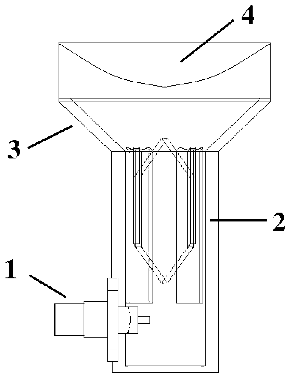
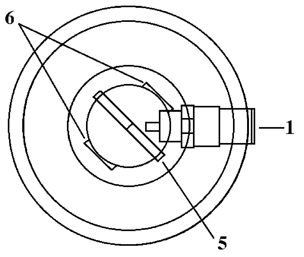
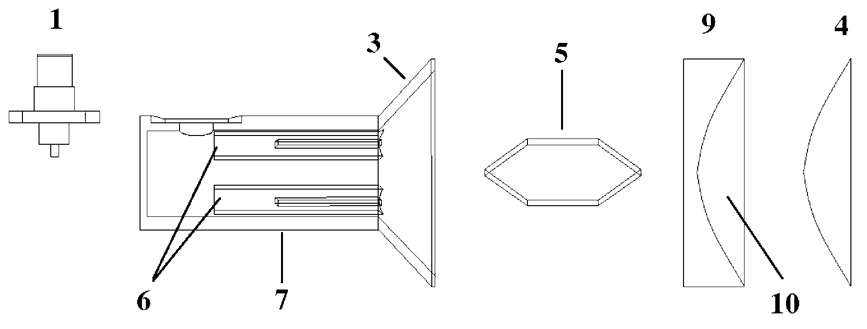
[0022] refer to Figure 1 ~ Figure 3 , the small circularly polarized horn antenna of the present invention mainly includes a coaxial-circular waveguide converter 1, a circular polarizer 2, a conical horn 3 and a dielectric lens 4. in:

[0023] The circular polarizer 2 is mainly composed of a dielectric insert 5 and two rectangular compensation slots 6, the dielectric insert 5 is a symmetrical hexagonal structure made of F4B-2 material, and is fixed in the circular waveguide 7 through a narrow slot; Two compensating rectangular compensating grooves 6 are symmetrically opened on the inner wall of the circular waveguide 7 , and are respectively located directly above and directly below the dielectric insert 5 .

[0024] The dielectric lens 4 adopts a hyperbolic structure of F4B-2 material, and is fixed in front of the conical horn 3 through a hard foam 9 . The dielectric constant of the rigid foam 9 is 1.08, and its structure is a cylinder with a groove 10 on the top surface. ...


PUM


Abstract

The invention discloses a small circularly-polarized horn antenna and mainly solves the problem that the prior art cannot simultaneously meet requirements of high power, high gain, wide band and circular polarization. The small circularly-polarized horn antenna comprises a coaxial-circular waveguide converter (1), a circular polarizer (2), a conical horn (3), a dielectric lens (4) and a circular waveguide (7), the circular polarizer (2) is mounted inside the circular waveguide (7) which is directly connected with the conical horn (3), the dielectric lens (4) is fixed in front of the conical horn (3), the conical-circular waveguide converter is mounted on the side wall of the circular waveguide (7), the circular polarizer (2) is composed of a symmetric hexagonal dielectric inserting piece (5) and two rectangular compensation grooves (6) which are fixed inside the circular waveguide (7), and the two compensation grooves are symmetrically arranged right above and right below of the dielectric inserting piece (5) inside the circular waveguide (7). The small circularly-polarized horn antenna has the advantages of wide band, good stability, high gain, large power capacity and good circular polarization characteristic.

Description

technical field [0001] The invention belongs to the field of microwave antennas, and relates to a circularly polarized horn antenna, which can be used as a feed source for various complex antennas or directly as an antenna, and can be widely used in wireless communication, radar and other fields. technical background [0002] With the rapid development of wireless communication technology, long-distance and large-range space communication systems such as mobile satellite communication systems have attracted more and more attention and applications. Among them, satellite communication is also an important part of the future global information superhighway. It is famous for its wide coverage and large communication capacity. It has the advantages of long communication distance, no limitation of geographical environment, excellent quality and high economic benefit. This puts forward higher requirements on the design of the antenna. Taking satellite communication as an exampl...

Claims


Application Information

Patent Timeline
IPC IPC(8): H01Q19/08H01Q15/24H01Q13/02
Inventor 雷振亚谢拥军杨锐李磊陈雷侯建强张嘉伟安翔
Owner XIDIAN UNIV
Why Eureka
Try Eureka