
Direct-current micro-grid system and control method thereof

A DC micro-grid and micro-grid technology, applied in the direction of AC network load balancing, single-network parallel feeding arrangement, photovoltaic power generation, etc. To solve problems such as limited power, it is beneficial to the design, improves the reliability of power supply, and has the effect of small power loss

Inactive Publication Date: 2013-08-07
JIAXING QINGYUAN ELECTRICAL TECH
View PDF3 Cites 50 Cited by
  • Summary
  • Abstract
  • Description
  • Claims
  • Application Information

AI Technical Summary

Problems solved by technology

Since the electric energy cannot be stored in the gas turbine system, peak shaving and valley filling as one of the control functions of the microgrid cannot be realized
Secondly, due to the large inertia of the gas turbine, it is impossible to achieve the second-level smooth control target of tie-line power
[0010] 2. When the micro-grid distributed power supply is an energy storage system, due to the limited power of the energy storage system, it is impossible to achieve long-term (such as tens of hours) island operation after a failure of the large power grid
[0011] 3. Existing technologies cannot simultaneously realize the rational configuration and application of megawatt-scale wind turbines and solar photovoltaic power generation devices within the microgrid

Method used


Image

  • Direct-current micro-grid system and control method thereof

Examples


Embodiment Construction

[0043] Below in conjunction with accompanying drawing, the present invention will be further described:

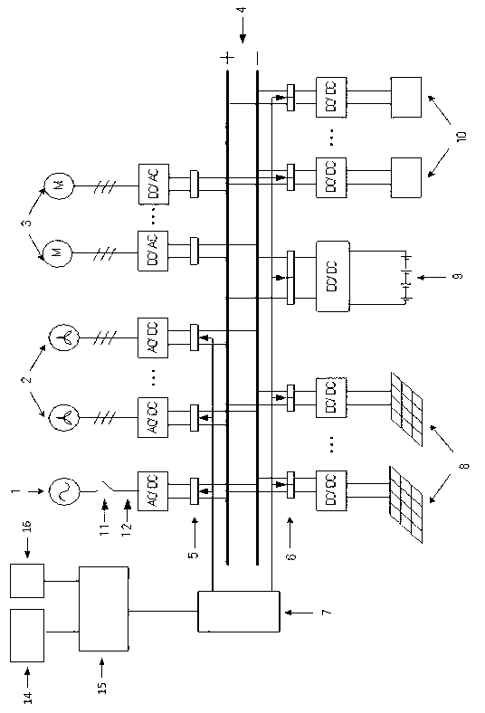
[0044] Such as figure 1 As shown, the DC microgrid system based on wind-solar energy storage includes: a bidirectional AC / DC rectifier / inverter 1 connected to the large power grid, at least one wind power generator 2 with an AC / DC rectifier, and a corresponding DC / DC rectifier. AC load of AC inverter 3, a DC power distribution line 4 (DC bus), AC / DC micro-grid protection device 5, DC / DC micro-grid protection device 6, micro-grid control system 7, with corresponding DC / DC modules Photovoltaic power generation device 8, energy storage device (battery) 9 and its corresponding DC / DC module, DC load 10 with corresponding DC / DC module, grid-connected switch 11, AC bus 12, urban micro-meteorological interactive system 14, upper-level dispatching Management system 15 and clock interaction system 16. The micro-grid protection device in this embodiment includes an AC / DC micro-grid...


PUM


Abstract

The invention relates to a direct-current micro-grid system and a control method thereof. The direct-current micro-grid system comprises a direct-current power distribution circuit, a bi-directional AC / DC (alternating current / direct current) rectifying / inverting device, a distributed energy generating device, an energy storing device, direct-current loads, alternating-current loads, a urban microclimate interactive system, a clock interactive system, a micro-grid control system and micro-grid protecting devices, an upper scheduling management system is arranged in the micro-grid control system so as to form layered management for micro-grid energy. The direct-current micro-grid control method includes: entering a grid connection mode or an island model according to working state of a large power grid, and determining the working states of the energy storing device and the distributed energy generating device according to information of the urban microclimate interactive system and the clock interactive system. The direct-current micro-grid system can independently supply power to the alternating-current and the direct-current loads and can be connected with a power grid to generate power according to processed result of urban microclimate interactive information, so that requirements on power supply for users are met, cost is reduced, designing, controlling, operation and maintenance of a micro-grid are benefited, and reliability, economy and efficiency of the micro-grid are effectively improved.

Description

technical field [0001] The invention relates to a DC micro-grid system and a control method thereof, and is mainly applicable to a DC micro-grid system connected to distributed power sources, wind and solar storage, and mains power multi-energy complementary. Background technique [0002] In recent years, with the increasing pressure on global resources and environment, smart grid has become a hot topic in the power industry, and is considered to be a grid development model that will change the future power system. [0003] The microgrid system is a highly independent decentralized power network, which is the basis of the smart grid. The system is composed of any combination of solar photovoltaic power generation, wind power generation, biomass power generation, gas power generation or diesel power generation, fuel cells, battery packs, etc., and then adds metering and control devices to form a self-contained system, independent of large power grids or intermittent and large...

Claims


Application Information

Patent Timeline
Patent Type & Authority Applications(China)
IPC IPC(8): H02J3/28H02J3/38
CPCY02E10/763Y02E70/30Y02E10/566Y02E10/563Y02E10/766Y02E10/56Y02E10/76
Inventor 邓玲慧王志新邹建龙
Owner JIAXING QINGYUAN ELECTRICAL TECH
Learn More