Vertebral body union internal fixation system

A fixation system and vertebral body technology, applied in the direction of internal fixator, fixator, internal bone synthesis, etc., can solve problems such as prolapse, artificial vertebral body sinking into the endplate of the upper and lower vertebral body, and increase the probability of nail breakage, etc.

Inactive Publication Date: 2013-08-14
BEIJING AKEC MEDICAL
View PDF10 Cites 8 Cited by
  • Summary
  • Abstract
  • Description
  • Claims
  • Application Information

AI Technical Summary

Problems solved by technology

However, clinical application and a series of biomechanical tests have shown that the traditional artificial vertebral body still has some problems to be solved in some aspects, especially the insufficient stability of postoperative axial rotation and the early integration with the upper and lower vertebral bodies. Low strength can easily lead to implant displacement or even prolapse. In order to ensure the bone volume of the central bone grafting hole, the design area of ​​the upper and lower endplates of the artificial vertebral body is reduced, and the supporting strength is insufficient, so that the artificial vertebral body is trapped in the endplates of the upper and lower vertebral bodies. Finally lost the ideal height
In order to reduce the impact of the above problems, people have to implement an anterior or posterior nail-plate or nail-rod fixation system while implanting the artificial vertebral body in order to provide stability in the early stage and during the fusion period, which virtually deteriorates the internal fixation. The mechanical environment of the screws in the system increases the probability of screw breakage and aggravates the phenomenon that the artificial vertebral body sinks into the upper and lower vertebral body endplates

Method used


Image

  • Vertebral body union internal fixation system
  • Vertebral body union internal fixation system
  • Vertebral body union internal fixation system

Examples


Embodiment Construction

[0062] The present invention will be described in detail below with reference to the accompanying drawings and examples.

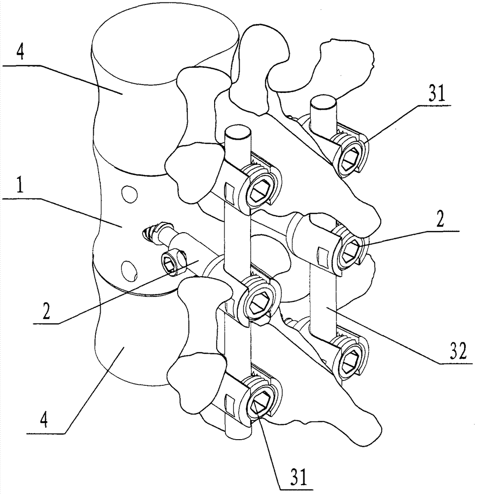
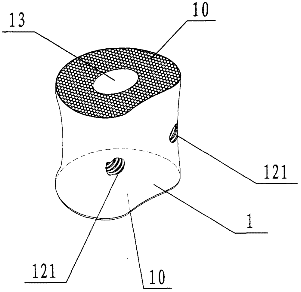
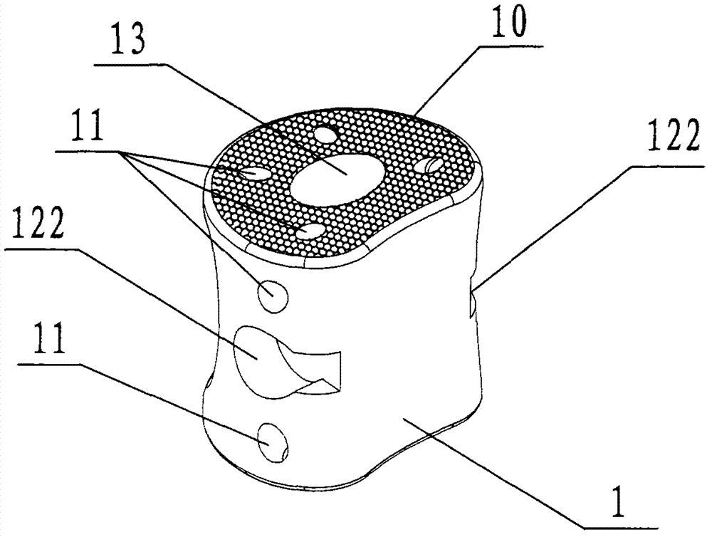
[0063] Such as figure 1 The shown vertebral body combined internal fixation system according to the present invention is set at the space left by the removed host vertebral body that cannot normally perform its own function due to tumor, trauma, or congenital disease. The combined vertebral body internal fixation system includes an artificial vertebral body main body 1, a vertebral body fixing screw 14, a vertebral body connector 2, a pedicle screw 31, and a longitudinal connecting rod 32; wherein the artificial vertebral body main body 1 is used for implantation to replace the excised or The missing host vertebral body segment is used to restore and reconstruct the physiological height of the spine and will form bony fusion with the upper and lower adjacent healthy vertebral bodies 4 in the future. The side forms the fixation and support function of the ...


PUM

PropertyMeasurementUnit
pore sizeaaaaaaaaaa
pore sizeaaaaaaaaaa
pore sizeaaaaaaaaaa

Abstract

The invention provides a vertebral body union internal fixation system which is used for performing internal fixation on a vertebral column. The vertebral body union internal fixation system comprises an artificial vertebral body main body, vertebral body fastening screws, a vertebral body connector, vertebral pedicle screws and a longitudinal connection rod. According to the vertebral body union internal fixation system, the artificial vertebral body main body, an adjacent upper vertebral body and an adjacent lower vertebral body are compactly fixed through the vertebral body fastening screws; fixation and support of vertebral column posterior are achieved through the vertebral pedicle screws and the longitudinal connection rod; and the artificial vertebral body main body and the longitudinal connection rod are compactly connected and fastened through the vertebral body connector. The vertebral body union internal fixation system is used for being inserted to replace resected or deleted parasitic vertebral body sections to enable the physiological height of the vertebral body to be recovered and rebuilt and forming synostosis between the adjacent upper vertebral body and the adjacent lower vertebral body in the future.

Description

technical field [0001] The invention relates to the field of orthopedic implants, and more specifically, relates to a vertebral body combined internal fixation system for internal fixation of the spine. Background technique [0002] In the treatment of human spinal diseases, spinal tumors, tuberculosis and severe fractures often cause vertebral body damage, which may lead to spinal cord nerve damage, so vertebral body resection has to be performed. After vertebral body resection, the spine needs to rebuild its stability. The emergence of vertebral body replacement provides an ideal method for the treatment of such diseases. Since the first report of vertebral body tumor resection and prosthetic replacement in the late 1960s, artificial vertebral bodies have been widely used clinically as a kind of effective vertebral body substitutes. However, clinical application and a series of biomechanical tests have shown that the traditional artificial vertebral body still has some pr...

Claims


Application Information

Patent Timeline
Patent Type & Authority Applications(China)
IPC IPC(8): A61B17/70A61F2/44A61L27/32A61L31/04
Inventor 刘忠军
Owner BEIJING AKEC MEDICAL
Why Eureka
Try Eureka