
Infusion speed detection method and infusion speed detection device

A speed detection and droplet technology, which is applied in measuring devices, fluid speed measurement, speed/acceleration/impact measurement, etc., can solve the problem of inaccurate number of pulse signals, distortion of double pulse signals, and inaccurate detection of droplet speed by infusion detection devices. Accurate and other problems, to achieve the effect of improving anti-interference performance and strong anti-interference ability

Inactive Publication Date: 2013-08-14
刘一
View PDF3 Cites 7 Cited by
  • Summary
  • Abstract
  • Description
  • Claims
  • Application Information

AI Technical Summary

Problems solved by technology

[0005] Second, when there is water mist on the inner wall of the Murphy's dropper, it will block part of the infrared light, and the output voltage of the infrared receiving phototransistor will not be 0V even if there is no droplet dripping
The above situations are very likely to cause severe distortion of the double pulse signal sent by the infrared receiving phototransistor, and the number of pulse signals detected within a certain period of time is inaccurate, which will eventually lead to inaccurate detection of the droplet velocity of the infusion detection device, and the alarm should not be reported. Misreporting from time to time or not reporting when the alarm should be reported, leading to serious medical accidents
[0006] Third, use a voltage comparator to judge whether there is a droplet passing through. The voltage threshold for comparison is fixed, and the threshold voltage cannot be changed according to the intensity of the surrounding ambient light and the water mist in the drip tube, which is easy to cause Misjudgment

Method used


Image

  • Infusion speed detection method and infusion speed detection device
  • Infusion speed detection method and infusion speed detection device
  • Infusion speed detection method and infusion speed detection device

Examples


Embodiment Construction

[0020] The present invention will be described in further detail below in conjunction with the accompanying drawings and examples, but the following examples should not be construed as limiting the present invention.

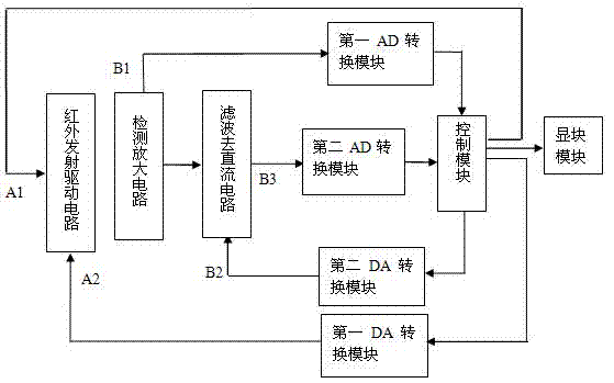
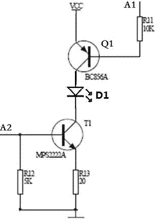
[0021] Such as figure 1 As shown, a device adopting the above detection method of infusion speed includes: an infrared LED drive circuit, a light detection amplifier circuit, a direct current removal circuit, a first AD conversion module, a second AD conversion module, a first DA conversion module, a second 2. DA conversion module and control module. The infrared light emitting diode driving circuit is connected with an IO port of the control module to control the alternating on and off of the infrared light emitting diodes; it is connected with the first DA conversion module to control the amplitude of the infrared light emitting diodes. The output of the light detection amplifier circuit is connected to the first AD conversion module, the output of the first ...


PUM


Abstract

The invention discloses an infusion speed detection method and an infusion speed detection device. The infusion speed detection device comprises an infrared light emitting diode, a infrared light emitting diode drive circuit, a photosensitive triode, an optical detecting and amplifying circuit, a direct current removing circuit, a control module and a display module. The infrared light emitting diode and the phototriode triode are respectively and symmetrically arranged on two sides of a Murphy's dropper wall, and the infrared light emitting diode is turned on and turned at a certain frequency. Every time when the infrared light emitting diode is turned on, transmission lights are converted into amplified signals through the optical detecting and amplifying circuit, the control module collects the signals and calculating direct-current capacity and controls lighting intensity for the next time according to the direct-current capacity. Alternating current is acquired after the direct current is removed, period time of the alternating current can be measured to calculate dripping speed of liquid dropping, and the dripping speed is displayed on the display module. Antijamming capability of the infusion speed detection method and the infusion speed detection device for medical infusion can be improved.

Description

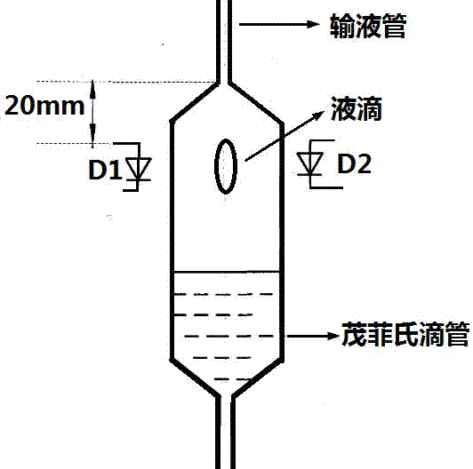
technical field [0001] The invention relates to an infusion speed detection method and a device thereof, belonging to the application field of medical infusion monitoring. Background technique [0002] At present, the detection device used for medical infusion generally adopts an infrared pair tube, that is, an infrared light-emitting diode and an infrared receiving photosensitive transistor are respectively symmetrically installed on both sides of the wall of the Murphy's dropper. Drops are detected. The working principle of this liquid drop detection is: use photoelectric detection technology to detect the infusion speed at the wall of Mufei's dropper, specifically, the infrared light-emitting diode emits infrared light, and the light passes through the Mufei's dropper to irradiate the infrared receiving photosensitive transistor , the infrared receiving phototransistor converts the received light signal into a photocurrent output. When there is no droplet passing throug...

Claims


Application Information

Patent Timeline
IPC IPC(8): A61M5/172G01P5/26
Inventor 刘一
Owner 刘一
Learn More