Machine tool table movement control method

A motion control, workbench technology, applied in the direction of manufacturing tools, metal processing equipment, metal processing machinery parts, etc., can solve problems such as reducing machine tool life, increasing scrap rate, affecting workpiece processing quality, etc., to reduce equipment costs and control costs. , Improve processing speed and efficiency, reduce the effect of external interference factors

Inactive Publication Date: 2013-08-14
NANJING UNIV OF TECH +3
View PDF5 Cites 6 Cited by
  • Summary
  • Abstract
  • Description
  • Claims
  • Application Information

AI Technical Summary

Problems solved by technology

Its defect is that there are detection errors, and when processing different workpieces, it is often necessary to manually adjust the upper and lower sensors. If the adjustment is not in place, there will be holes, fluffing and other phenomena, which will affect the processing quality of the workpiece and increase the scrap rate.
Moreover, the movement of the existing workbench is usually a constant acceleration and deceleration movement according to the set parameters. Sometimes the movement distance of each section of the workpiece to be processed is quite different. At this time, the set fixed speed parameters cannot meet the processing requirements at all. When the distance is short, it will have to decelerate without accelerating, which will cause the vibration of the table to affect the machining accuracy and reduce the life of the machine tool; or when the distance is relatively long, the acceleration and deceleration will be slow, and after the fixed position occurs, the spindle will not be able to follow the predetermined trajectory. Changing processing, causing workpiece damage or scrapping
[0003] It can be seen that there are many problems that need to be solved urgently in the existing control method of the table movement, and the improvement of the traditional control method has encountered a bottleneck

Method used


Image

  • Machine tool table movement control method
  • Machine tool table movement control method

Examples


Embodiment Construction

[0018] In order to make the object, technical solution and advantages of the present invention clearer, the present invention will be further described in detail below in conjunction with the accompanying drawings and embodiments. It should be understood that the specific embodiments described here are only used to explain the present invention, not to limit the present invention.

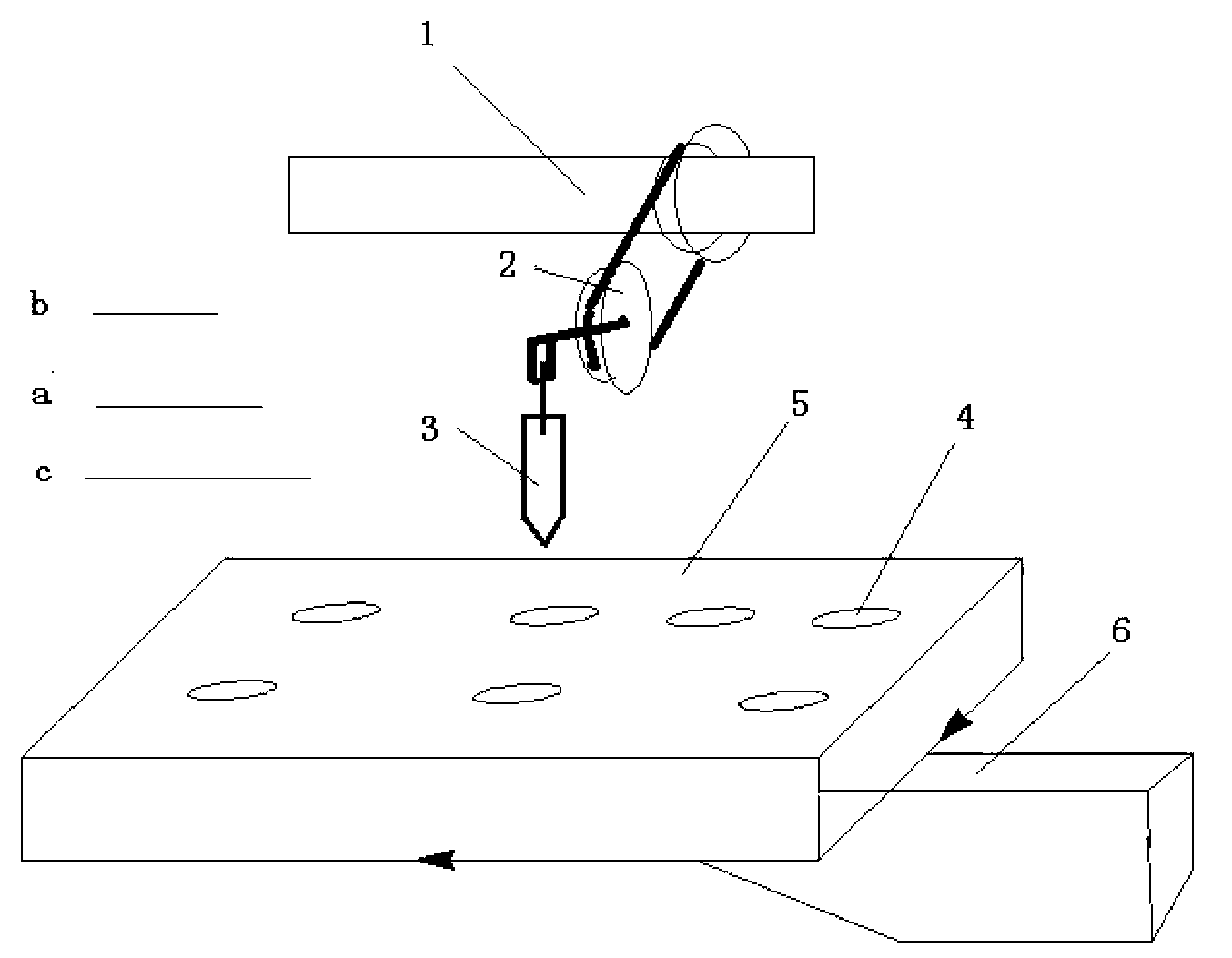
[0019] Such as figure 1 As shown, it is the tufting machine controlled by the method of the present invention. The main shaft 1 drives the cam 2 to move by rotation, and then drives the drill bit 3 to reciprocate between the high position and the low position through the connecting rod, and the drill bit 3 moves up and down to complete the process of punching or tufting . Among the figure 4 is the hole drilled on the workpiece, 5 is the workpiece, and 6 is the workbench. The critical point a (workpiece critical surface) marked in the figure refers to the point where the drill bit is infinitely cl...


PUM


Abstract

A machine tool table movement control method includes the steps: acquiring a spindle safety following area; acquiring the current spindle speed in real time; calculating the offset angle of a spindle according to response lag time of a table servo driver and the spindle speed to obtain a new spindle following area for controlling a table; and dividing the new spindle following area into an accelerating section, a constant-speed section and a decelerating section in sequence, correspondingly changing the impulsing frequency of the table servo driver by a controller when the angle of the spindle is respectively positioned in the accelerating section, the constant-speed section and the decelerating section, and controlling the table to respectively run in accelerating, constant-speed and decelerating modes. By the aid of characteristics of the spindle following area, the rotating angle of the spindle serves as a triggering condition of the controller without depending on an upper sensor and a lower sensor, external interference factors are decreased, so that control is more accurate, damage and the scrap rate of workpieces are reduced, and the moving area is divided into three sections which are respectively controlled so that more stable movement of the table is ensured.

Description

technical field [0001] The present invention relates to a motion control method of a machine tool workbench, and more specifically, to a method for realizing tracking of a part of the spindle area and the workbench position. Background technique [0002] In the hair planting and brush making industries, the main shaft rotates quickly and drives the drill bit to reciprocate up and down through the connecting rod and the cam. The drill bit completes a cycle of motion every time the main shaft rotates (ie 360°)—from a high position (the highest point) to a low position (the lowest position). Point) and then return to the high position (the highest point), while the drill bit rotates at high speed driven by the motor to drill the workpiece. The worktable with the workpiece moves under the main shaft according to the predetermined trajectory. When the drill bit leaves the previous drilling hole, the worktable starts to move to the next hole position, and then the drill bit starts...

Claims


Application Information

Patent Timeline
Patent Type & Authority Applications(China)
IPC IPC(8): B23Q1/30
Inventor 舒志兵李泽仁吴晨军徐昆江小玲
Owner NANJING UNIV OF TECH
Why Eureka
Try Eureka