A stirring type fluorination electrolytic cell

A fluorinated electrolytic cell and electrolytic cell technology, applied in electrolytic components, electrolytic process, electrolytic organic production, etc., can solve the problems of small contact probability between electrolyte and electrode plate, low electrolytic fluorination reaction efficiency, long induction period, etc. The effect of reducing the reaction induction period, eliminating the dead tank phenomenon, and increasing the single tank output

Active Publication Date: 2016-03-23
湖北诺邦科技股份有限公司
View PDF6 Cites 0 Cited by
  • Summary
  • Abstract
  • Description
  • Claims
  • Application Information

AI Technical Summary

Problems solved by technology

However, the traditional electrolytic cell has the following disadvantages: the HF in the cell does not flow, and the electrolyte dissolved in the HF has a small contact with the plate, so the efficiency of the electrolytic fluorination reaction is low; the induction period of the reaction electrolytic fluorination reaction is long, generally 3 Days - 5 days, and the dead slot phenomenon is more frequent, after the voltage is applied, there is no current input

Method used


Image

  • A stirring type fluorination electrolytic cell
  • A stirring type fluorination electrolytic cell
  • A stirring type fluorination electrolytic cell

Examples


Embodiment Construction

[0017] The technical solutions of the present invention will be clearly and completely described below in conjunction with the accompanying drawings of the present invention. Obviously, the described embodiments are only a part of the embodiments of the present invention, rather than all the embodiments. Based on the embodiments of the present invention, all other embodiments obtained by those of ordinary skill in the art without creative work shall fall within the protection scope of the present invention.

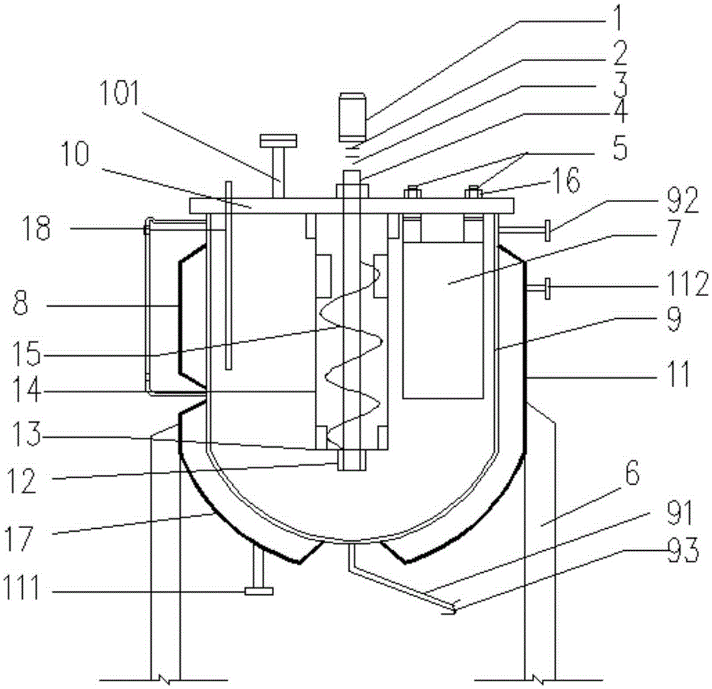
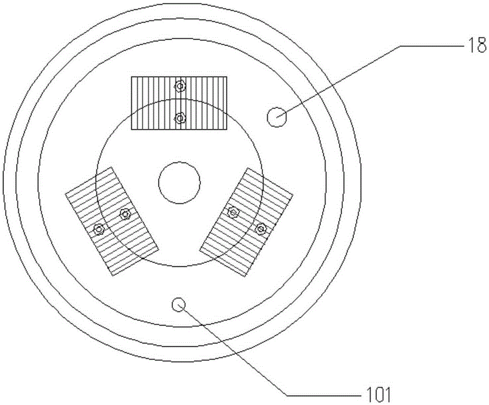
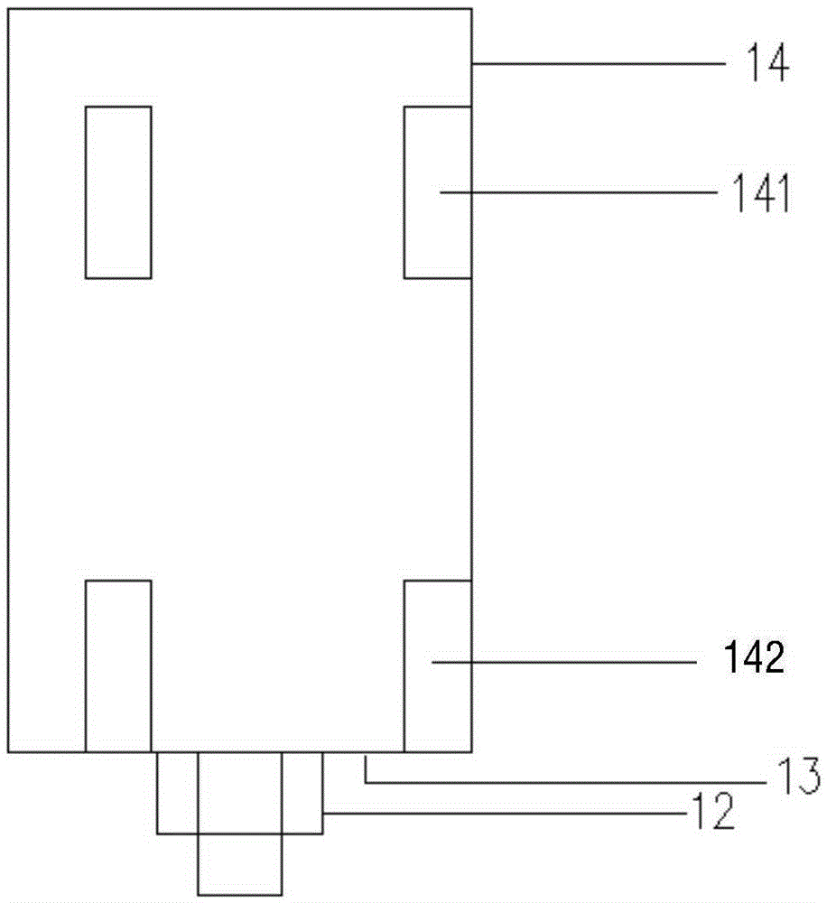
[0018] according to figure 1 , figure 2 , image 3 As shown, as a preferred embodiment, an agitated fluorination electrolytic cell consists of a motor 1, a coupling 2, a stirring shaft 3, a shaft seal 4, an electrode column 5, a foot 6, an electrode bundle 7, and a liquid level gauge 8. , The electrolytic cell 9, the electrolytic cell cover plate 10, the electrolytic cell jacket 11, the shaft sleeve 12, the blind plate 13, the deflector 14, the stirring blade 15, the insula...


PUM


Abstract

A stirring type fluorination electrolytic cell, which consists of a motor, a shaft coupling, a stirring shaft, a shaft seal, an electrode column, an electrode bundle, an electrolytic cell, an electrolytic cell cover plate, an electrolytic cell jacket, a shaft sleeve, a blind plate, and a guide tube , a stirring paddle, and an insulating gasket. The agitated fluorination electrolytic cell provided by the present invention makes the material dissolve and disperse more uniformly in the whole system, and at the same time, the fluorination reaction is carried out in the electrolytic cell, which reduces the reaction induction period. The reaction induction period is reduced from 3-5 days to one day, and the dead tank phenomenon is basically eliminated, and the number of times to clear the tank due to the treatment of dead tanks is reduced. Before adopting the stirring tank, the dead tank was 3-4 times a year. After the present invention is adopted, There is no dead tank phenomenon, the material consumption is reduced by more than 20%, the output of a single tank is increased by 30%, the polymer generated in the electrolytic tank is reduced, the tank cleaning time is doubled, and the labor intensity of manual tank cleaning is reduced.

Description

Technical field [0001] The invention relates to the technical field of an electrolytic cell for organic electrochemical synthesis, in particular to a stirred type fluorinated electrolytic cell. Background technique [0002] There are very few fluorine-containing organics in nature. How to introduce fluorine into organics has become an urgent problem that people need to solve. The preparation of organic fluorides can use F 2 Direct fluorination, XeF also available 2 , Hypofluoric acid, high-valent metal fluorides, N2F compounds and other fluorinating reagents indirect fluorination method. These chemical fluorination methods are complex in reaction and operation, and require harsh equipment; the fluorinating reagents used are highly toxic or extremely unsafe, and some are very expensive; and it is difficult to control the amount of fluorine added, and it is difficult to obtain the target product. Therefore, people have to find other methods. In 1941, American chemist Simons invent...

Claims


Application Information

Patent Timeline
Patent Type & Authority Patents(China)
IPC IPC(8): C25B3/08C25B9/00C25B3/28
Inventor 熊国建陈建生
Owner 湖北诺邦科技股份有限公司
Why Eureka
Try Eureka