
Large-sized quick opening-and-closing gate-ball combined valve

A gate valve and ball valve technology, which is applied in the field of large-diameter and fast-opening and closing gate valves and ball valves, can solve the problems of no soft seal, low working pressure of the valve, uneven sealing force of the valve core, etc., so as to achieve easy replacement and work High pressure and reliable sealing effect

Inactive Publication Date: 2013-08-14
吴植仁
View PDF1 Cites 5 Cited by
  • Summary
  • Abstract
  • Description
  • Claims
  • Application Information

AI Technical Summary

Problems solved by technology

[0015] However, the above component force valve still has the following disadvantages: (1) The cam is used as the side pressure actuator, and the sealing force is limited. In addition, after the enlargement, the sealing force of the valve core is uneven, so the working pressure of the valve is not high. Practice has proved that , its cost performance is not as good as the existing butterfly valve; (2) the sealing part does not use a soft seal, and the required machining accuracy is still very high; (3) a large operating space is required for installation, and when it is used for buried pipe networks, it needs larger valve well
Therefore, the prototype of the patent failed to be industrialized after the successful trial production

Method used


Image

  • Large-sized quick opening-and-closing gate-ball combined valve
  • Large-sized quick opening-and-closing gate-ball combined valve
  • Large-sized quick opening-and-closing gate-ball combined valve

Examples


Embodiment 1

[0021] Embodiment 1 Large-diameter lifting gate valve

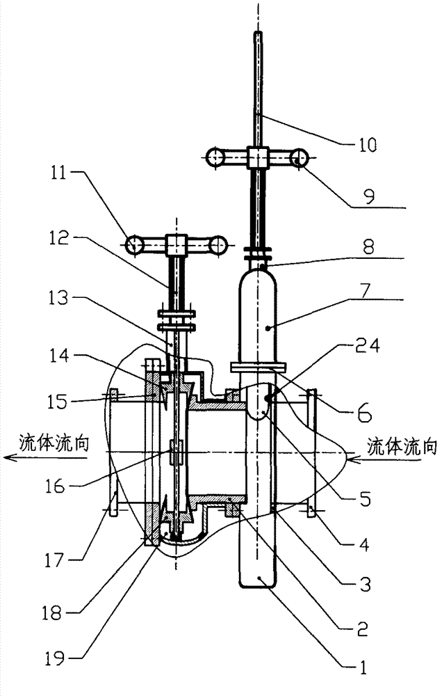
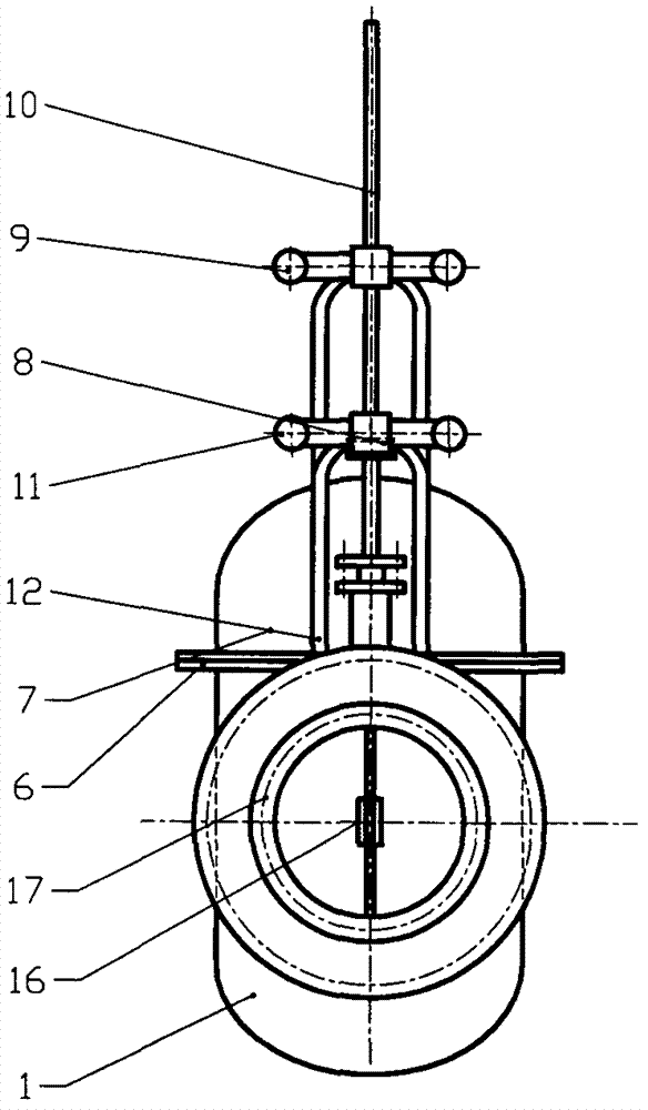
[0022] figure 1 It is a front section view of a large diameter lift gate valve, figure 2 yes figure 1 side view. The valve is composed of two parts: the spool chamber and the wedge-shaped slider chamber. The spool chamber is composed of the spool chamber casing (lower part) 1, the spool chamber casing (upper part) 7, the valve seat 3, the inlet flange 4, the gate plate 5, the middle flange 6, the opening and closing upper seal 8, the opening and closing hand Wheel 9, opening and closing valve stem 10 is formed. The wedge-shaped slider chamber is composed of a sealing handwheel 11, a sealing valve stem 12, a sealing upper seal 13, a wedge-shaped slider (upper) 14 and a wedge-shaped slider (lower) 18, a floating pressure ring 2, a fixed pressure ring 15, Coupling sleeve 16, outlet flange 17, wedge-shaped slider chamber shell 19 is made up of.

[0023] Wedge-shaped slide blocks 14 and 18 slide up and down against the ...

Embodiment 2

[0027] Embodiment 2 Large diameter swing gate valve

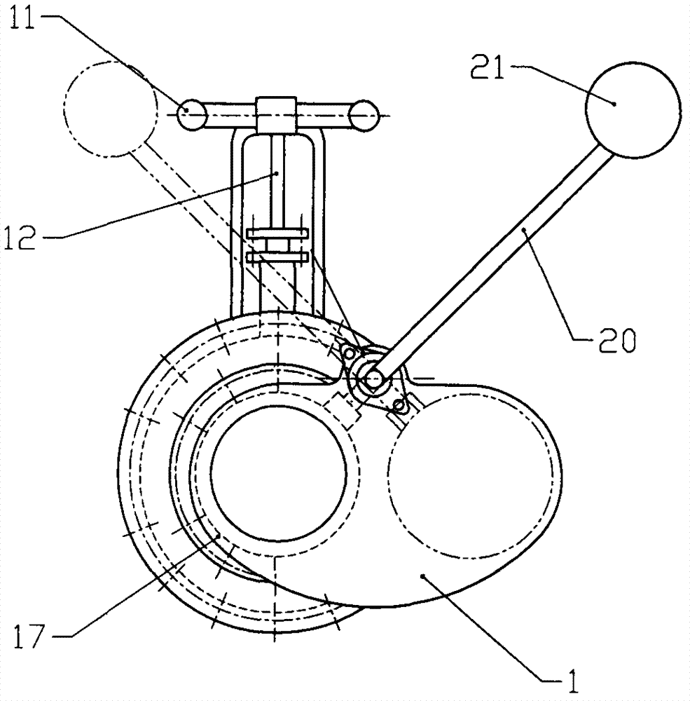
[0028] image 3 is the front view of the large diameter swing gate valve in the closed position, Figure 4 yes image 3 side view. The structure of the wedge slider chamber and figure 1The same, and the shell of the spool chamber is in the shape of a waist, in which the gate can swing left and right. The opening and closing valve stem and the pendulum shaft (not shown in the figure) that drive the gate plate 5 to swing are connected through the opening and closing upper seal 8 and the pendulum handle 20, and are equipped with a counterweight 21 for labor saving and self-locking. Figure 4 The pendulum handle of the middle drawing solid line and the flashboard 5 corresponding to the counterweight are in the closed position, while the dotted line is in the open position.

[0029] Opening of the valve: Turn the sealing hand wheel 11, and through the sealing valve stem 12, the wedge-shaped sliders slide opposite to each ot...

Embodiment 3

[0031] Embodiment 3 large diameter ball valve

[0032] Figure 5 It is the front cross-sectional view of the large-diameter ball valve when it is open. Figure 6 It is the front section view of the large diameter ball valve when it is closed. The structure of the wedge slider chamber and figure 1 The same, and the valve core 22 is spherical, which is different from ordinary ball valves. The valve seat 3 is not a spherical surface but a conical surface, which is more convenient for processing. Same as ordinary ball valves, the top end of the opening and closing valve stem 10 is milled into a square, driven to rotate by a handle (not shown in the figure), and the dynamic sealing is guaranteed by the opening and closing upper seal 8, and the lower end is provided with an anti-blowing structure. Different from ordinary ball valves, when the ball valve is in the closed position, the top of the spherical valve core 22 is provided with a chute, and the spherical valve core 22 can ...


PUM


Abstract

The invention provides large-sized quick open-and-close gate-ball combined valve. The gate-ball combined valve is composed of component parts including a valve casing, a valve spool, a valve seat, a sealing pair, an upper seal and an actuating mechanism and the like. The large-sized open-and-close gate-ball combined valve is characterized in that one sealing element in the sealing pair is made of soft sealing materials, when the valve is on or off, no sliding but only motion in a vertical direction or an opposite direction exists between the sealing pair to ensure the soft sealing materials to be free of rubbing force. In order to achieve above characteristics, the adopted technical scheme includes that sealing force and on-or-off force transmitted to the valve spool are completed by two independent mechanisms, the sealing force of a valve is not preset, an on-or-off process of the valve is performed according to steps of 1), on: releasing the valve spool / value seat prior to moving the valve spool (moving after releasing); and 2), off: moving the value spool prior to sealing the valve spool / valve seat (tightening after moving). The large-sized quick open-or-close gate-ball combined valve has the advantages of reliable sealing, quick on-or-off, high working pressure, low requirement for machining accuracy, low cost, non-preset of the sealing force, small abrasion of sealing surfaces, long service life, easy replacement, small on-or-off torque and small coverage of operation space. Besides, the large-sized quick open-and-close gate-ball combined valve is applicable to various pipe networks built on stilts, ground surfaces and buried deep and the like.

Description

Technical field [0001] The invention relates to a gate valve and a ball valve with a large diameter and rapid opening and closing, and its working pressure includes low, medium and high pressure. Background technique [0002] At present, there are three main types of large-diameter valves: gate valve, ball valve and butterfly valve. The gate valve has a mature structure and reliable sealing, but in large-diameter pipelines, especially when transporting dangerous media (such as gas, flammable and explosive gases), it has gradually been replaced by high price, complex structure and poor sealing performance, opening and closing torque and service life. It is not as good as the ball valve and butterfly valve of the gate valve. The main reason is that the opening and closing speed of the gate valve is too slow. Once the pipe bursts, the medium cannot be cut off quickly. When the pipe is inflammable, explosive or toxic, it will cause the accident to expand further and cause more...

Claims


Application Information

Patent Timeline
IPC IPC(8): F16K3/00F16K5/06F16K3/30F16K5/20F16K5/08
Inventor 吴植仁
Owner 吴植仁
Learn More