Plasma heavy oil burner

A heavy oil combustion and plasma technology, applied in the direction of burners, combustion methods, combustion types, etc., can solve the problems of waste of resources, pollution of the environment, high requirements, etc., and achieve the effect of reducing pollution and clean combustion

Active Publication Date: 2013-08-14
南通东湖国际商务服务有限公司
View PDF9 Cites 5 Cited by
  • Summary
  • Abstract
  • Description
  • Claims
  • Application Information

AI Technical Summary

Problems solved by technology

The current heavy oil burner uses heavy oil fuel mixed with heavy oil and diesel oil. In the heavy oil burner, the heavy oil fuel is sprayed and mixed with the internal air for direct combustion. The current heavy oil burner has high requirements for oil products and needs to be used before use. The disadvantages of dehydration treatment of oil, but also the disadvantages of insufficient combustion, waste of resources and pollution of the environment

Method used


Image

  • Plasma heavy oil burner
  • Plasma heavy oil burner

Examples


Embodiment Construction

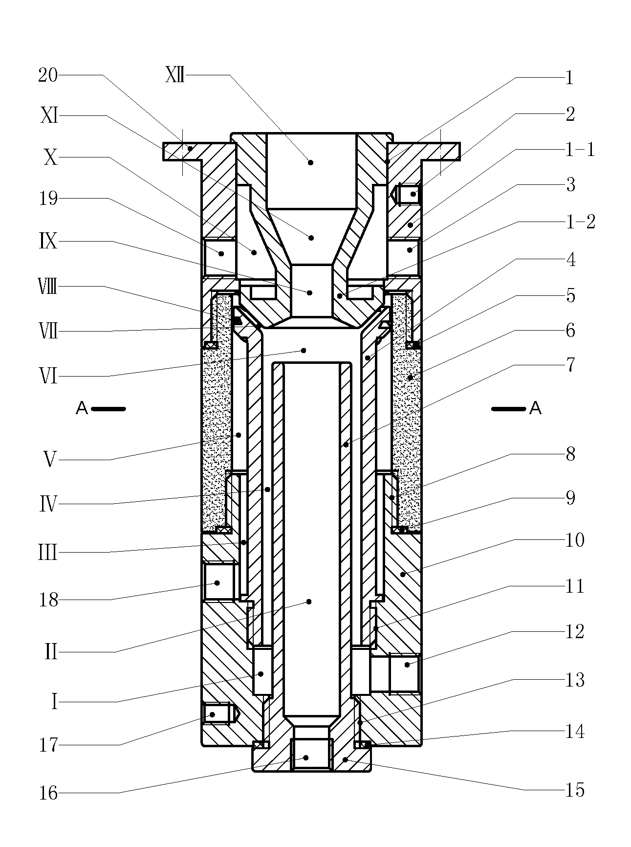
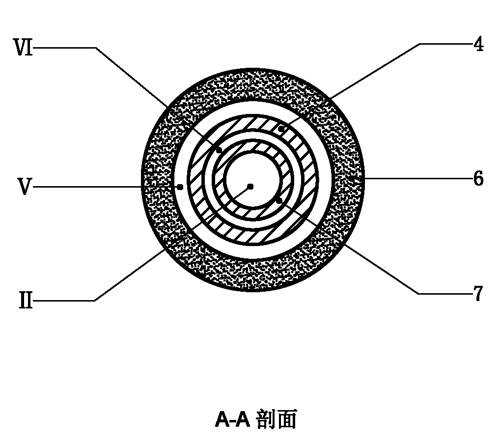
[0014] Example figure 1In the embodiment shown, the plasma heavy oil burner is mainly composed of the anode (1), the insulating connector (6), the cathode (4), the inner sleeve (7) and the rear seat (10), wherein the anode (1) , the insulating connector (6), the cathode (4), the inner sleeve (7) and the rear seat (10) are coaxially arranged, the insulating connector (6) is in a cylindrical structure, and the rear end of the anode (1) is connected through insulation The piece (6) is connected to the external connection port (8) at the front end of the back seat (10), the cathode (4) is set in the inner space of the insulating connector (6), and the lower end of the cathode (4) is connected to the back seat (10) On the internal connection port a (11), the inner sleeve (7) is a tubular body structure, and the inner sleeve (7) extends from the rear end of the rear seat (10) and enters the inner cavity (IV) of the cathode (4) , the rear end of the inner sleeve (7) is connected to ...


PUM


Abstract

The invention discloses a plasma heavy oil burner, and relates to burning equipment. The plasma heavy oil burner mainly comprises an anode, an insulation connecting piece, a cathode, an inner sleeve and a rear seat, wherein the rear end of the anode is connected with the rear seat through the insulation connecting piece; the cathode is arranged in an inner space of the insulation connecting piece; the lower end of the cathode is connected to the rear seat; the inner sleeve extends into and enters an inner cavity of the cathode from the rear end of the rear seat; an axis through hole of the anode forms a compression duct; a cooling water sleeve is arranged in the anode; a torch outlet is formed at the front end of the anode; a tapered protruding structure at the rear end of the anode extends into the inner space of the insulation connecting piece; the upper end of a cylinder body of the cathode is bell-mouthed; a rotational flow groove is formed at the outer edge of a bell mouth; a space between the inner edge of the bell mouth at the upper end of the cathode and the tapered protruding structure at the rear end of the anode forms an annular airflow channel; the rear seat is provided with a revolving body structure; and an annular oil cavity is arranged in the revolving body structure, and communicated with the inner cavity of the cathode. The plasma heavy oil burner allows heavy oil fuel to be burnt completely, improves the burning efficiency of heavy oil, and reduces the environmental pollution.

Description

technical field [0001] The invention relates to burner equipment, in particular to a heavy oil burner. Background technique [0002] Heavy oil is the remaining heavy oil after gasoline and diesel are extracted from crude oil. It is characterized by large molecular weight and high viscosity. The low calorific value of heavy oil fuel is 38.5-44MJ / kg. With the gradual depletion of oil resources, the development of industry and the accelerated increase of automobiles, light oil will not be able to meet the demand, and heavy oil combustion technology must be developed to fill the energy gap. The current heavy oil burner uses heavy oil fuel mixed with heavy oil and diesel oil. In the heavy oil burner, the heavy oil fuel is sprayed and mixed with the internal air for direct combustion. The current heavy oil burner has high requirements for oil products and needs to be used before use. The disadvantages of dehydration treatment of oil, but also the disadvantages of insufficient co...

Claims


Application Information

Patent Timeline
Patent Type & Authority Applications(China)
IPC IPC(8): F23D11/00F23D11/44
Inventor 周昀煜
Owner 南通东湖国际商务服务有限公司
Why Eureka
Try Eureka