Low cost trough type solar concentrator

A trough-type solar energy and concentrator technology, which is applied in the field of solar concentrators, can solve problems such as many welding points of truss beams, slow production speed, and low solar energy, so as to save manpower and time, reduce construction costs, optimize The effect of the assembly process

Inactive Publication Date: 2015-06-10
BEIJING JINGCHENG KAITUO NEW ENERGY TECH
View PDF8 Cites 0 Cited by
  • Summary
  • Abstract
  • Description
  • Claims
  • Application Information

AI Technical Summary

Problems solved by technology

Its disadvantages are: firstly, it consumes a lot of steel, and it is heavy and costly; secondly, the structure is complex, truss welding requires positioning, marking, and welding must be done manually, and there are many welding points for truss beams and rods, which cannot be automated. Time-consuming, labor-intensive, and high processing costs; according to statistics, ten skilled workers can assemble a group in three days, so the processing technology of this traditional structure is not conducive to industrialized mass production
Its disadvantage is that the stamped support arm 200 is a single-piece structure with poor stability. In order to ensure the support strength, the arc shape of its root must be set to not less than half a circle, so that the two opposite support arms can embrace each other. The moment axis of the transmission mechanism, and the thickness of the support arm must be set to more than 5mm, the steel used is more, the cost is high, and the weight is heavy; secondly, the production press needs to be large, resulting in high production cost; the production speed is slow if the press is too large
[0005] Since solar energy itself is a low energy source, it is difficult to collect
A MW solar thermal power station needs to install nearly 300 groups (12 meters per group) of trough solar concentrators. Generally, the minimum installed capacity of a solar thermal power station is more than 20 MW. It can be seen that small-scale production cannot meet actual needs. , it is imperative to develop low-cost, mass-produced trough solar concentrators

Method used


Image

  • Low cost trough type solar concentrator
  • Low cost trough type solar concentrator
  • Low cost trough type solar concentrator

Examples


Embodiment Construction

[0031] The specific implementation manners of the present invention will be further described in detail below in conjunction with the accompanying drawings and embodiments. The following examples are used to illustrate the present invention, but are not intended to limit the scope of the present invention.

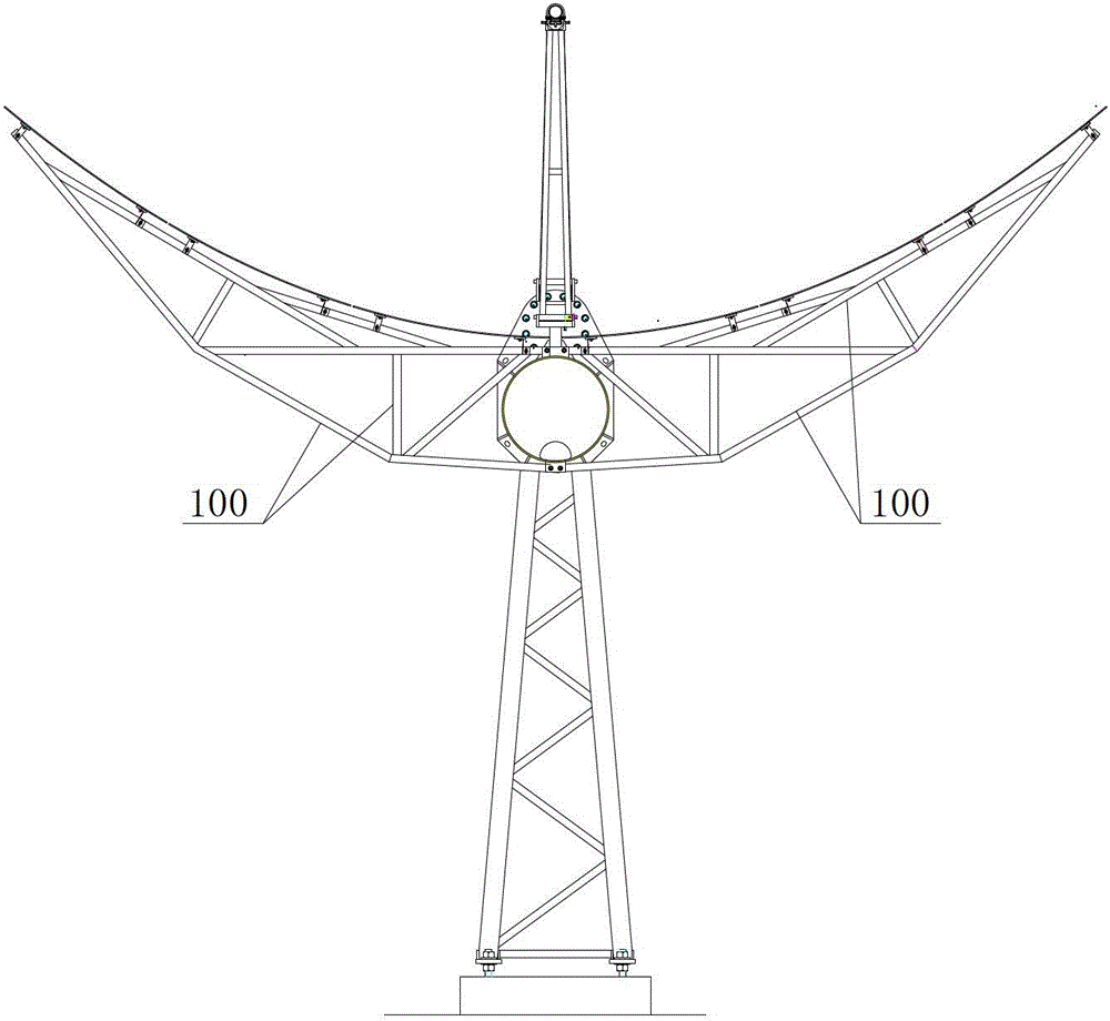
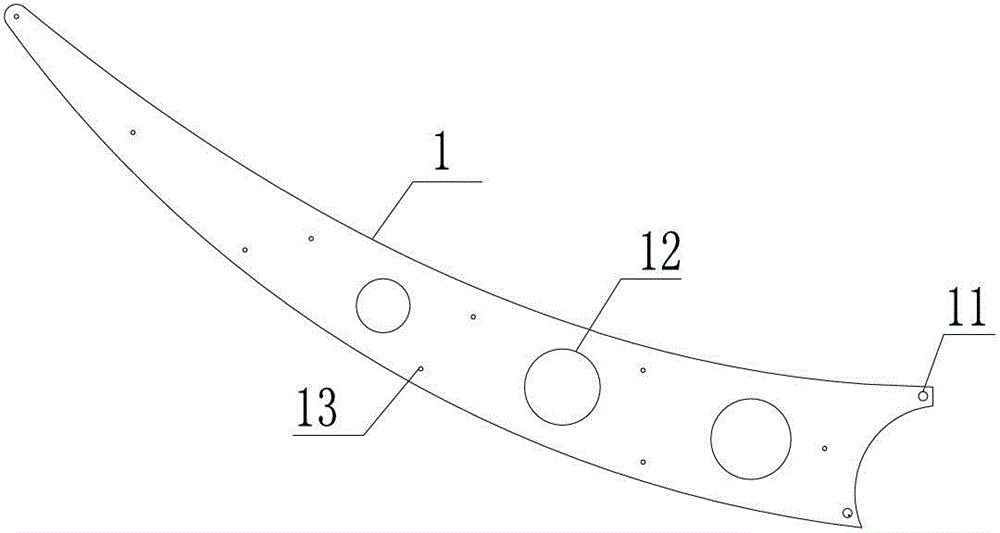
[0032] Such as Figure 3-6 It is Embodiment 1 of the present invention, which innovates the shape and structure of the support arm, that is, the installation process, etc., specifically:

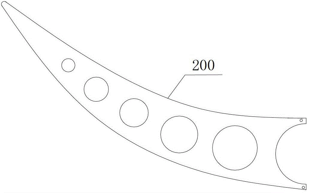
[0033] Such as image 3 As shown, the schematic diagram of the arm structure of the trough solar concentrator of the present invention, the arm 1 is a plate-type arm formed by stamping, so as to save processing technology and optimize the assembly process; specifically, the arm 1 is in the shape of Scimitar shape, that is, it is bent in a direction parallel to the plate surface, and the curvature of the curvature is adapted to the curvature of the mirror 2 of the mirror mechanism, so a...


PUM


Abstract

The invention provides a low cost trough type solar concentrator which comprises a reflector mechanism and a transmission mechanism. Reflectors of the reflector mechanism are fixedly arranged on a torque shaft of the transmission mechanism through support arms which are plate type support arms through stamping forming; every two support arms are connected into a group; and two grouped support arms are respectively arranged on adjacent end portions of adjacent reflectors. The low cost trough type solar concentrator has the advantages of enabling sizes of the support arms to be significantly reduced on the basis of guaranteeing installation requirements such as the strength and then saving materials and costs, being convenient to assemble, being capable of achieving automatic assembly operation, enabling the assembly process to be optimized, saving the manpower and time and enabling the construction costs of the low cost trough type solar concentrator to be further reduced due to the fact that an innovative design is performed on shapes and structures of the support arms.

Description

technical field [0001] The invention relates to a solar concentrator, in particular to a low-cost trough solar concentrator. Background technique [0002] In my country's Twelfth Five-Year Plan, solar thermal power generation is the focus of development, but cost has become a bottleneck hindering solar thermal power generation. How to reduce the cost of solar thermal power generation has become a research project that is competing around the world. At present, trough solar concentrators can be roughly divided into two types: tube truss type and stamping type due to the difference in support arms. [0003] Most of the existing trough solar concentrators in my country are tube truss type. Such as figure 1 As shown, its truss type support arm 100 is mainly welded by truss beams and rods. Its disadvantages are: firstly, it consumes a lot of steel, and it is heavy and costly; secondly, the structure is complex, truss welding requires positioning, marking, and welding must be d...

Claims


Application Information

Patent Timeline
Patent Type & Authority Patents(China)
IPC IPC(8): F24J2/10F24J2/52F24S23/70
CPCF24S23/74F24S30/425Y02E10/47
Inventor 郑麒韩笑
Owner BEIJING JINGCHENG KAITUO NEW ENERGY TECH
Why Eureka
Try Eureka