Adjustable wireless charging coil and application method thereof

A wireless charging and adjustable technology, applied in the direction of coils, circuits, current collectors, etc., can solve the problems of manufacturing and design errors, difficulty in controlling the qualified rate of finished products, and not being adopted, so as to achieve improved wireless transmission efficiency and high accuracy of adjustment range , the effect of convenient adjustment

Inactive Publication Date: 2013-08-14
HUNAN UNIV OF HUMANITIES SCI & TECH
View PDF3 Cites 13 Cited by
  • Summary
  • Abstract
  • Description
  • Claims
  • Application Information

AI Technical Summary

Problems solved by technology

However, due to the manufacturing process and other reasons, it is very difficult to design the resonant frequency of the transmitting and receiving coils to be the same in the system design in mass production, and the qualified rate of finished products is difficult to control, and the circuit itself, parasitic capacitance and external objects will all affect the resonant frequency of the coil changes, resulting in a decrease in charging efficiency and a waste of electric energy
[0003] In the coil design, the method of adjusting the coil resonance frequency can also be changed by adding inductance or capacitance to the circuit, or adding ferrite, metal sheets, etc. outside the coil to change the resonance frequency of the coil, but the above methods have no The quality factor of the

Method used


Image

  • Adjustable wireless charging coil and application method thereof
  • Adjustable wireless charging coil and application method thereof
  • Adjustable wireless charging coil and application method thereof

Examples


Embodiment 1

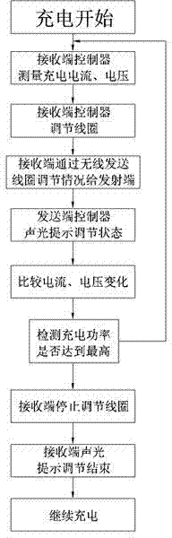
[0017] Embodiment 1 When the device is located at the wireless charging receiving end:

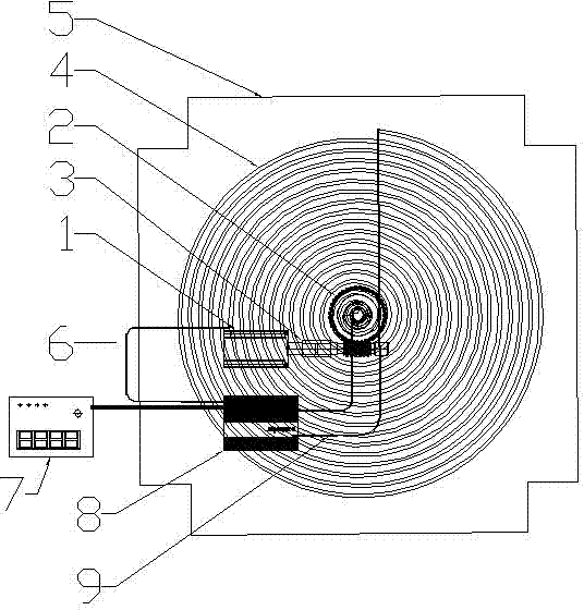
[0018] See attached figure 1 And attached figure 2 The wireless charging coil device described in this embodiment includes a stepping motor 1, a worm wheel 2, a worm 3, a mainspring coil 4, a coil bottom plate 5, a motor drive line 6, a reminder device 7, a controller 8, and the coil is connected Line 9, wherein the stepper motor 1 can be replaced by a DC motor or other motors. In this example, a stepper motor is selected, and the angular displacement is controlled by controlling the number of pulses, so as to achieve the purpose of accurately positioning the rotation angle. The stepping motor 1 is installed on the lower end of the coil base plate 5, and the coil base plate 5 can be made into shapes such as squares and circles according to actual needs, and its manufacturing materials include shielding materials such as high-frequency ferrite and aluminum plates. The coil bottom plate 5...

Embodiment 2

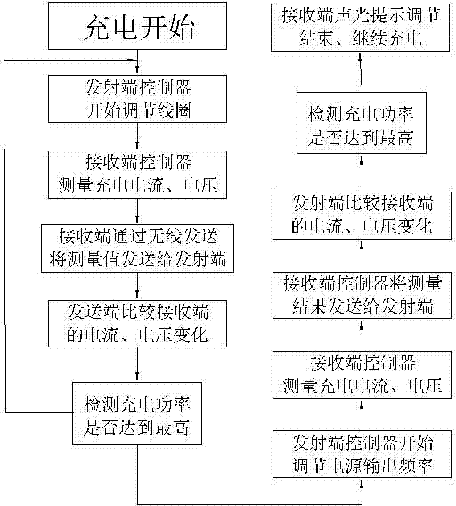
[0027] Embodiment 2 When the device is located at the wireless charging transmitter:

[0028] See attached figure 1 And attached image 3 The difference between this embodiment 2 and embodiment 1 is that the controller 8 mainly includes the high-frequency power output module of the coil, the drive of the motor, the wireless communication module and the drive circuit of the display panel. The controller can be placed on the bottom plate in order to avoid interference under. The high-frequency power supply output module outputs high-frequency alternating current to connect the outer ring and the inner ring of the coil 4 respectively through the coil connection; the motor drive mainly controls the rotation of the motor; the rotation of the motor drives the rotation of the turbine and the worm and causes the change of the coil structure; The wireless communication module at the transmitting end is responsible for wireless signal communication with the wireless module at the rece...


PUM

PropertyMeasurementUnit
The inside diameter ofaaaaaaaaaa
Outer diameteraaaaaaaaaa

Abstract

The invention provides an adjustable wireless charging coil which comprises a clockwork coil, a coil baseplate, a reminding device and a controller, wherein the clockwork coil is manufactured into a helical clockwork shape by adopting conductive material; a stepping motor is mounted at the lower end of the coil baseplate, and is driven by and connected with a motor driving wire of the controller; an output shaft of the stepping motor is connected with a worm through a shaft coupling device; the worm is meshed with a worm wheel; a shaft lever of the worm wheel penetrates through the coil baseplate and is connected with the inner coils of the clockwork coil mounted on the coil baseplate through a cap, the inner coils of the clockwork coil are connected simultaneously; the outer end of the clockwork coil penetrates through the coil baseplate and is connected with a power line of coil connecting lines; the controller is mounted on the coil baseplate; and the reminding device is connected onto the controller. Through the adoption of the structure of the adjustable wireless charging coil, the adjustment is convenient and fast, and the precision of the adjusting range is high.

Description

technical field [0001] The invention relates to the technical field of wireless charging, in particular to an adjustable wireless charging coil and a method for using the same. Background technique [0002] The technology for wireless charging mainly has the following four methods: electromagnetic induction method, radio wave method, magnetic resonance method and electric field coupling method. Among them, the magnetic resonance method was verified in 2007 by Marin Soljacic, a physicist at the Massachusetts Institute of Technology (MIT), and has received widespread attention since then. The technology utilizes the principle of resonance, which is the efficient transfer of energy between two objects vibrating at the same frequency. The magnetic resonance method can transmit charges in the air between the charger and the device, and the coil and capacitor form a resonance between the charger and the device to realize the technology of efficient power transmission. When two o...

Claims


Application Information

Patent Timeline
IPC IPC(8): H01F5/00H02J7/00H02J17/00H02J50/12
Inventor 陈新吴永祥宋英博周元玲
Owner HUNAN UNIV OF HUMANITIES SCI & TECH
Why Eureka
Try Eureka