Gas dual-cycle radiant tube heating device

A technology of radiant tube heating and gas circulation, which is applied in the field of gas radiant tube heating, and can solve problems such as carburization, harm to the human body, and easy local burning

Inactive Publication Date: 2013-08-21
UNIV OF SCI & TECH BEIJING
View PDF8 Cites 9 Cited by
  • Summary
  • Abstract
  • Description
  • Claims
  • Application Information

AI Technical Summary

Problems solved by technology

[0004] For the gas radiant tube heating device, in the flame zone, the temperature of the flue gas is high, correspondingly forming a high temperature zone on the wall surface of the radiant tube, and after the flame zone, the temperature of the flue gas decreases, correspondingly forming a low temperature zone on the wall surface of the radiant tube, therefore There are problems of uneven temperature along the length of the pipe and local high temperature; while the material of the pipe body, surface temperature distribution, use environment, etc., the inner surface of the pipe is in direct contact with the combustion flame and high-temperature flue gas, which is easy to be locally burned and oxidized at the same time In the case of carburizing and nitriding, the thermal stress caused by uneven surface temperature distribution will deform the tube body, which also seriously affects the service life of the radiant tube; nitrogen-containing gas will form NOx under high temperature and oxygen conditions, and its There are three main generation mechanisms: thermal type, instantaneous response type and fuel type. Discharging into the atmosphere will pollute the environment and even endanger the human body

Method used


Image

  • Gas dual-cycle radiant tube heating device
  • Gas dual-cycle radiant tube heating device
  • Gas dual-cycle radiant tube heating device

Examples


Embodiment Construction

[0024] The specific technical solutions of the present invention will be further described below in conjunction with the accompanying drawings.

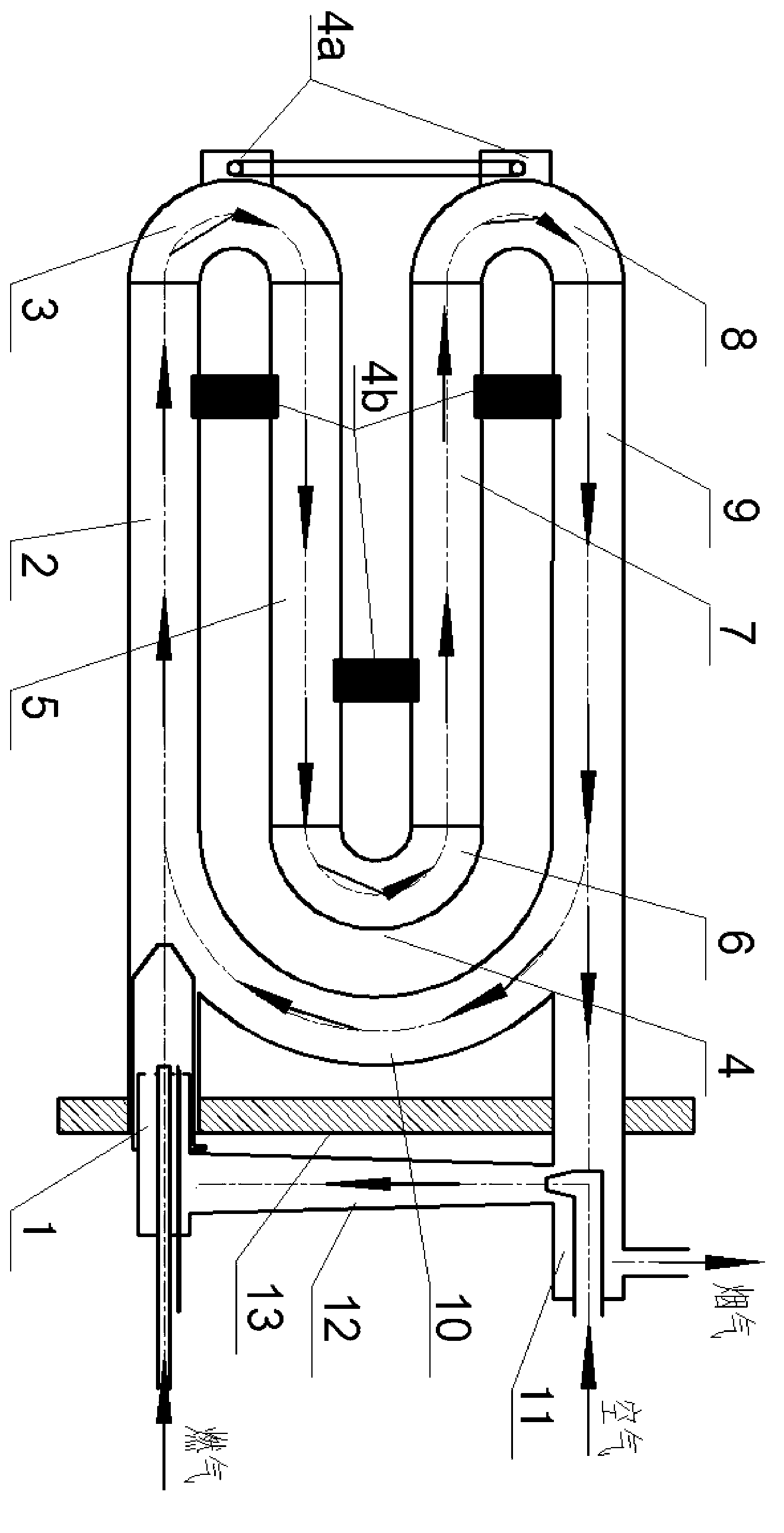
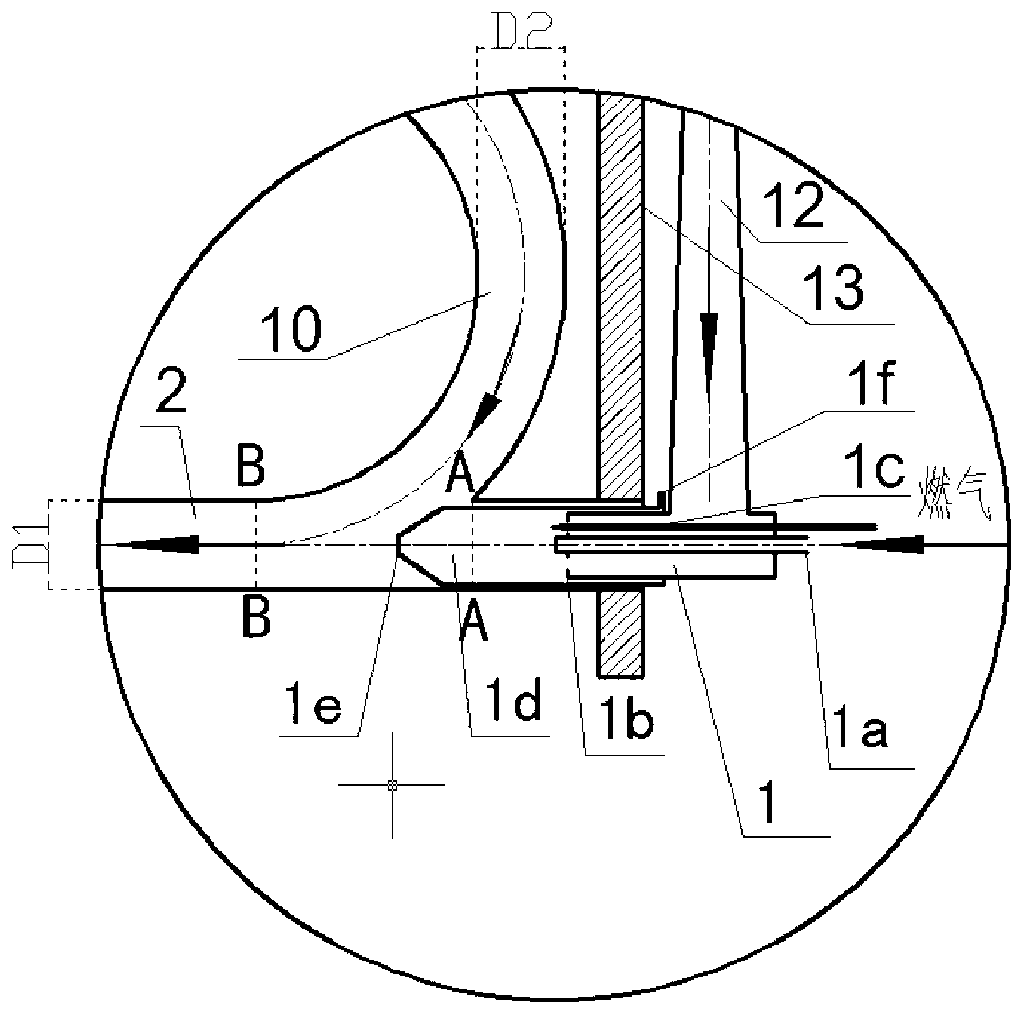
[0025] Such as Figure 1-3 Shown is the structure schematic diagram of the gas double-circulation radiant tube heating device of the present invention, and this device comprises the inner ring gas circulation pipeline part that is placed in the furnace and the outer ring gas circulation pipeline part outside the furnace,

[0026] The inner ring gas circulation pipeline part includes a first straight pipe 2, a first bent pipe 3, a second straight pipe 5, a second bent pipe 6, a third straight pipe 7, a third bent pipe 8, and a fourth straight pipe 9 and flue gas return pipe 10;

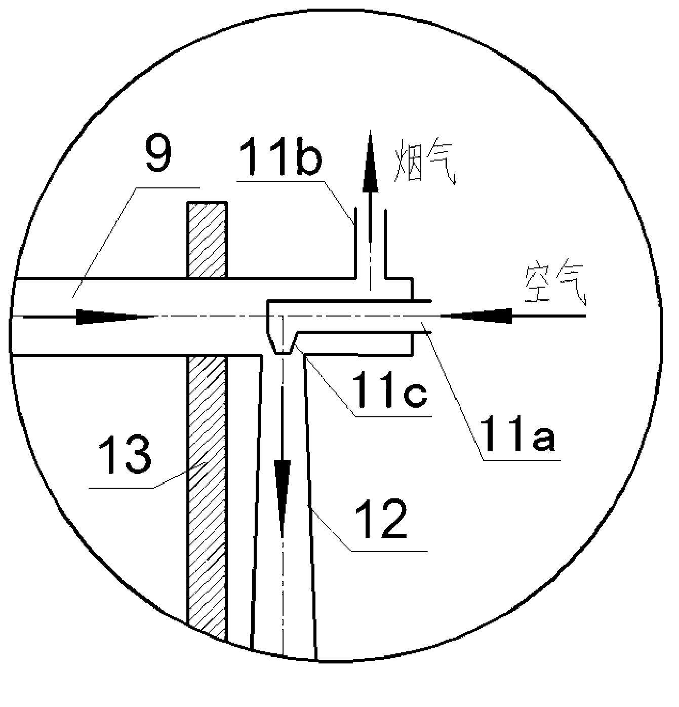
[0027] The outer ring gas circulation pipeline part includes a burner 1, an air-smoke transfer device 11, and a mixed gas delivery pipe 12; the air-smoke transfer device 11 includes an air inlet 11a, an air tapered outlet 11c and a smoke outlet 11b, The bur...


PUM


Abstract

The invention discloses a gas dual-cycle radiant tube heating device. The part in a furnace of the device is a closed inner-ring gas circulating line composed of a first straight tube, a first bend, a second straight tube, a second bend, a third straight tube, a third bend, a fourth straight tube and an added smoke return tube, and the part outside the furnace of the device is an outer-ring gas circulating line composed of an empty smoke switching device, a mixed gas conveying tube and a nozzle. The heating device overcomes the defects that the temperature distribution of a radiant tube along the length direction is non-uniform and the local temperature is high. Returned smoke and combustion flame are mixed through inner-ring gas circulating so as to reduce the core temperature of flame, enhance the uniformity of the surface temperature distribution of the radiant tube, prolong the service life, and reduce the generation of thermal NOx; since the smoke return tube is added, the effective radiation heat exchange area in the furnace is enlarged, and the outer-ring gas circulating is capable of effectively improving the pre-heating temperature of gas, reducing the oxygen content in air and realizing low-temperature combustion, thereby increasing the heat efficiency while alleviating pollution.

Description

[0001] technical field [0002] The invention belongs to the technical field of gas radiant tube heating, in particular to a gas double-cycle radiant tube heating device suitable for heat treatment under a protective atmosphere, which can be used in various industrial furnaces that require high heating quality of products. Background technique [0003] Metal heat treatment can make the heated metal have good properties, and most of the heating process needs to be carried out in a controlled atmosphere. At present, the most common heat treatment heating methods are electric heating and gas heating. Gas radiant tubes can meet the requirements of heat treatment heating. Compared with heating, gas radiant tube heating has the advantages of high heat utilization rate of primary energy, large thermal power per unit surface area, and low operating cost. [0004] For the gas radiant tube heating device, in the flame zone, the temperature of the flue gas is high, correspondingly form...

Claims


Application Information

Patent Timeline
Patent Type & Authority Applications(China)
IPC IPC(8): C21D1/52
Inventor 冯俊小曹亚平
Owner UNIV OF SCI & TECH BEIJING
Why Eureka
Try Eureka