Prestretching-pretwisting type full-bridge 2D electro-hydraulic proportional directional valve

An electro-hydraulic proportional and full-bridge technology, which is applied in the direction of valve details, multi-way valves, valve devices, etc., can solve the problem of leakage flow of the pilot control stage that cannot work normally, large flow rate of the pilot-control electro-hydraulic proportional valve, stuck pilot Problems such as the level control oil circuit can be overcome to overcome adverse effects, the structure is simple, and the effect of proportional control function is realized

Inactive Publication Date: 2013-08-21
ZHEJIANG UNIV OF TECH
View PDF0 Cites 32 Cited by
  • Summary
  • Abstract
  • Description
  • Claims
  • Application Information

AI Technical Summary

Problems solved by technology

[0009] In order to overcome the existing electro-hydraulic proportional valve's susceptibility to friction, hydraulic power and oil pollution, the phenomenon of "stuck" and the loss of pressure in the oil circuit of the pilot and control stage or the pressure is too low make the entire valve unable to work normally and the pilot and control stage Due to the large leakage flow rate, the present invention provides an ordinary pilot-controlled electro-hydraulic proportional valve that not only has the characteristics of large flow rate and high working pressure, but also can be realized like a direct-acting proportional valve under zero pressure (pressure loss). Pretension-pretwist type full-bridge 2D electro-hydraulic proportional directional valve with proportional control function

Method used


Image

  • Prestretching-pretwisting type full-bridge 2D electro-hydraulic proportional directional valve
  • Prestretching-pretwisting type full-bridge 2D electro-hydraulic proportional directional valve
  • Prestretching-pretwisting type full-bridge 2D electro-hydraulic proportional directional valve

Examples


Embodiment Construction

[0026] The present invention will be further described below in conjunction with the accompanying drawings.

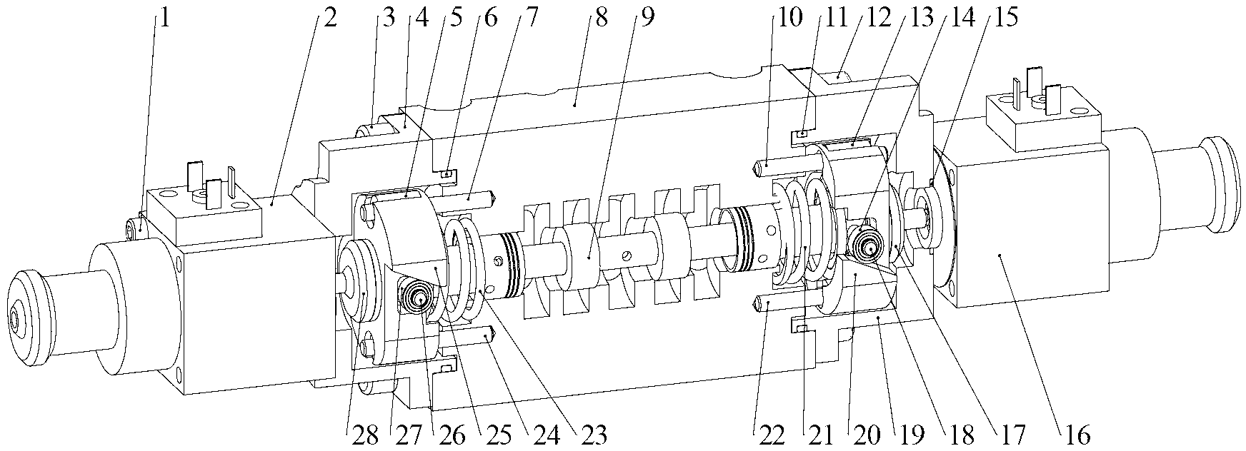
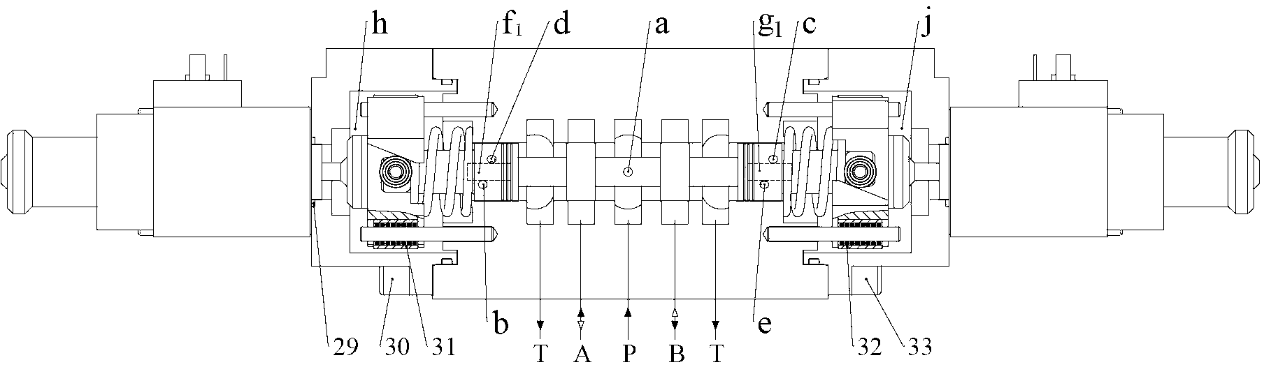
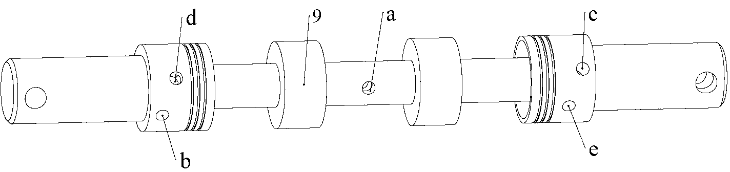
[0027] refer to Figure 1 to Figure 10 , a pre-tensioned-pre-twisted full bridge 2D electro-hydraulic proportional reversing valve includes screws 1, 3, 12, 30, 33, linear electro-mechanical converters 2, 16, end covers 4, 19, linear bearings 5 , 13, 31, 32, cylindrical compression spring 21, 23, O-ring 6, 11, 15, 29, pin 7, 10, 22, 24, valve body 8, valve core 9, rolling bearing 14, 27, 36, 38, top cover 17,28, bearing pin 18,26, sliding wedge 20,25, tightening screw 34, steel ball 35, sleeve 37,39.

[0028] The pre-tension-pre-twist type full-bridge 2D electro-hydraulic proportional reversing valve consists of three parts: 2D valve, linear electro-mechanical converter and compression-torsion coupling.

[0029] The 2D valve part includes a spool 9 and a valve body 8, the spool 9 is rotatably and axially slidably arranged in the inner hole of the valve body 8, the le...


PUM


Abstract

Provided is a prestretching-pretwisting type full-bridge 2D electro-hydraulic proportional directional valve. Two ends of the 2D valve are respectively connected with linear electrical machinery converters through pressure-torsion couplings and springs, a spring 4 is mounted between a valve body and a slide wedge, and the pre-compression amount of the spring 4 is slightly larger than the travel of a valve core. A left sensitive cavity and a right sensitive cavity are formed between end portion shoulders and the valve body and between the slide wedge and the valve boy. A pair of high-pressure hole and low-pressure hole (a, b) and a pair of high-pressure hole and low-pressure hole (c, d) are formed in the end portion shoulders respectively, and the high-pressure hole and low-pressure hole (a, b) and the high-pressure hole and low-pressure hole (c, d) are respectively communicated with a port P and a port T through the inner holes of the valve core. A sensing channel c and a sensing channel f are formed in two ends of the wall of the inner hole of the valve body respectively, and are respectively communicated with the left sensitive cavity g and the right sensitive cavity h. The high-pressure holes and the lower-pressure holes of the end portion shoulders cross with the sensing channels to form two tiny opening areas, the two tiny opening areas are connected in series to form hydraulic resistance half bridges, and the pressure of the two end sensitive cavities is respectively controlled by the hydraulic resistance half bridges at two ends.

Description

technical field [0001] The invention belongs to an electro-hydraulic proportional valve in the field of fluid transmission and control, in particular to an electro-hydraulic proportional reversing valve. Background technique [0002] Electro-hydraulic servo control technology organically combines the advantages of fluid transmission control technology and information electronic technology, and has been applied in important national strategic military industrial fields such as aerospace, cutting-edge weapons, steel, and electric power generation, and has achieved rapid success. However, the electro-hydraulic servo valve also has defects such as poor anti-pollution ability, large pressure loss (7MPa) in the valve, high manufacturing cost and maintenance cost, and large system energy loss. Due to the many defects of the electro-hydraulic servo valve, its fast response performance cannot be widely used in general industrial equipment. At the same time, the traditional electro-h...

Claims


Application Information

Patent Timeline
Patent Type & Authority Applications(China)
IPC IPC(8): F16K11/02F16K31/06
CPCF15B13/02F16K11/078F16K31/06F15B13/0406F15B2211/30575F16K31/52483F15B13/0433Y10T137/86694Y10T137/86702Y10T137/8671F16K11/0716F16K11/07
Inventor 阮健励伟孟彬左强陈莹
Owner ZHEJIANG UNIV OF TECH
Why Eureka
Try Eureka