A metal plate defect detection device and method under high-speed motion state

A high-speed motion, metal plate technology, applied in the direction of measuring devices, analytical materials, material magnetic variables, etc., can solve problems affecting mechanical strength and size, inability to achieve online detection, inability to online detection, etc., to improve the sensitivity of the instrument and the detection speed. Fast, fast effects

Inactive Publication Date: 2015-08-26
CHINA UNIV OF MINING & TECH
View PDF6 Cites 2 Cited by
  • Summary
  • Abstract
  • Description
  • Claims
  • Application Information

AI Technical Summary

Problems solved by technology

However, the surface of the test piece is guaranteed to be clean and smooth before the ultrasonic method is tested, and it is necessary to coat the surface of the test piece with a coupling agent, which cannot be affected by external factors when it is damp or polluted, otherwise it will affect the mechanical strength and dimensional stability of the tested object, and cannot Realize online detection
The X-ray method is carried out by using the attenuation of rays in the material and the photochemical effect on certain objects. It has high sensitivity, intuitive reliability, and good repeatability, but the detection cost is high and the time is long, and a large number of films need to be experienced. Staff identification, unable to detect online, and need to take radiation protection measures
The working principle of the eddy current method is Faraday's law of electromagnetic induction, which has the advantages of low cost, fast speed, and no need for coupling media. However, the eddy current method is affected by the skin effect and is only suitable for non-destructive testing and evaluation of the surface and near-surface conditions of metal sheets.

Method used


Image

  • A metal plate defect detection device and method under high-speed motion state
  • A metal plate defect detection device and method under high-speed motion state
  • A metal plate defect detection device and method under high-speed motion state

Examples


Embodiment Construction

[0018] The present invention will be further described below in conjunction with the accompanying drawings.

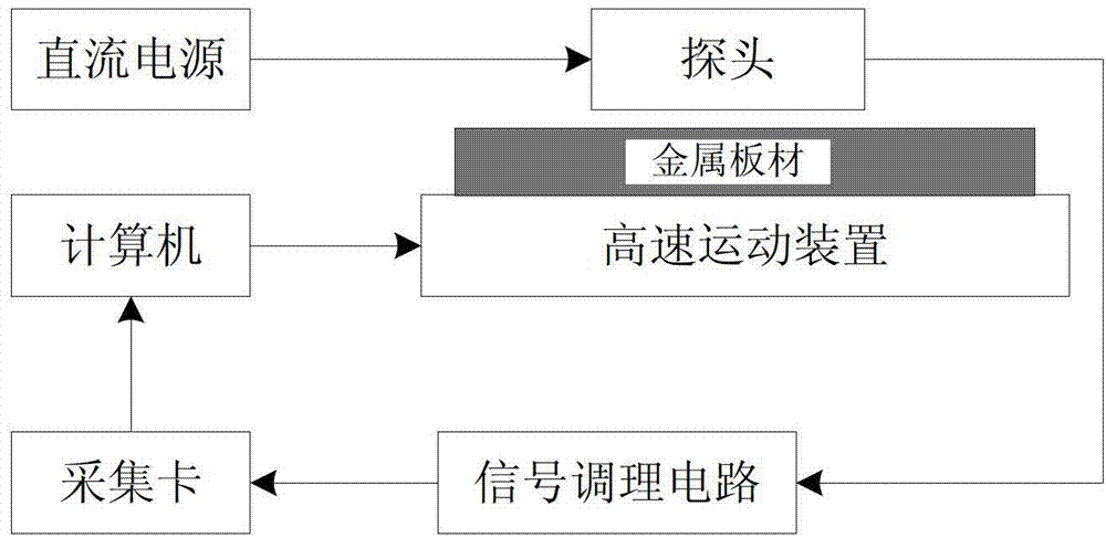
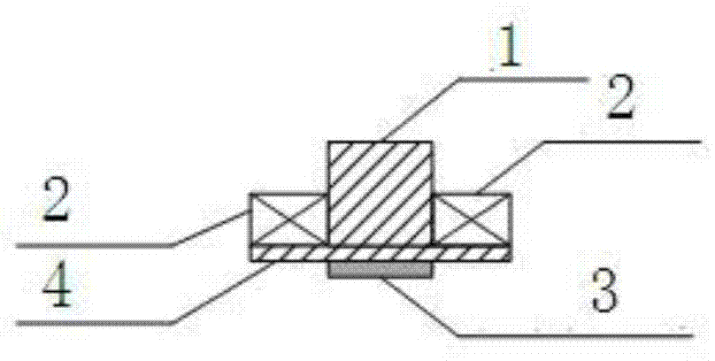
[0019] like figure 1 As shown in the figure, the defect detection device for metal plates in the high-speed motion state of the present invention includes a DC power supply, a probe, a signal conditioning circuit, a capture card, a computer and a high-speed motion device; the DC power supply is connected to the input end of the probe, and the output end of the probe is connected to the input end of the signal conditioning circuit , The output end of the signal conditioning circuit is connected to the computer through the acquisition card, and the computer is connected to the input end of the high-speed motion device; figure 2 and image 3 Shown: the probe is an eddy current probe, consisting of an iron core 1, a coil 2, a Hall sensor 3 and a circuit board 4, the coil 2 is wound on the iron core 1, the Hall sensor 3 is fixed on the circuit board 4, and the circuit boa...


PUM


Abstract

The invention discloses a metal sheet defect detection device and method in a high-speed motion state. The device mainly comprises a computer, a high-speed motion device, a probe, a signal processing circuit, an acquisition card and a direct-current power source. According to the device, the probe is driven by the direct-current power source, a metal sheet is fixed above the high-speed motion device and passes through the probe at constant speed; when a magnetic field is cut as a result of relative movement between the metal sheet and the probe, an induced current is generated in the metal sheet; the induced current then generates a secondary magnetic field so as to change the size of a space magnetic field; when a defect exists in the metal sheet, the induced current varies so as to change the size of the magnetic field; a magnetic field sensor in the probe measures the change of the magnetic field; output signals pass through the signal processing circuit and the acquisition card and are then output to the computer; and the defect of the metal sheet can be recognized through data analysis. The device and method can be applied to nondestructive detection and evaluation of the quality and in-service state of the metal sheets, and have wide market prospect.

Description

technical field [0001] The invention relates to a defect detection device and method for a metal plate in a high-speed motion state, and belongs to the technical field of non-destructive detection. Background technique [0002] Sheet metal is a raw material with huge demand in basic industries, and an important structural material for construction machinery, spacecraft, military aircraft, rockets, missiles, ships and ships. However, for different application fields, the metal sheet must be strictly tested according to the requirements during the processing process to see if it contains defects that affect the performance. Non-destructive testing technology is a testing method that does not damage the workpiece and does not affect the performance. It is widely used in product design, material selection, processing and manufacturing, finished product inspection, inventory re-inspection, maintenance and other fields. At present, non-destructive testing has become a mandatory m...

Claims


Application Information

Patent Timeline
Patent Type & Authority Patents(China)
IPC IPC(8): G01N27/90G01N27/904
Inventor 曹丙花范孟豹李威杨雪锋王禹桥王文龙刘芳沁樊启高罗成名尹亚丹
Owner CHINA UNIV OF MINING & TECH
Why Eureka
Try Eureka