

Novel conical scanning antenna
A cone scanning and antenna technology, applied in the field of radar tracking, can solve the problems of unstable work, large mechanical vibration, complex structure, etc., and achieve the effect of low product cost, high cost and great difficulty.
- Summary
- Abstract
- Description
- Claims
- Application Information
AI Technical Summary
Problems solved by technology
Method used
Image

Examples
Embodiment Construction
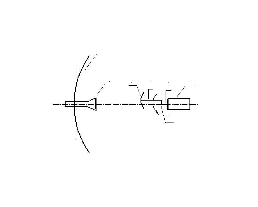
[0009] Such as figure 1 As shown, an embodiment of the present invention includes a paraboloid 1, a feed source 2, and a secondary surface 3, and is also provided with a motor 4 and a crankshaft 5. The motor 4 includes a motor shaft, and the first end 6 of the crankshaft 5 Connected with the motor shaft, the axis of the motor shaft coincides with the axis of the parabola, the concave surface apex of the secondary surface 3 is provided with a mounting seat, the second end 7 of the crankshaft 5 extends along the axis of the secondary surface 3 and Installed on the mounting base, the secondary surface 3 is driven by the motor 4 to realize the defocused rotary cone sweep.
[0010] The principle is: on the basis of the classic card antenna, the communication in motion is realized through the defocus rotation of the sub-surface 3. The degree of defocus depends on the depth of the cone-sweeping intersection level. The secondary surface 3 rotates around the axis of the paraboloid 1 a...
PUM
 Abstract
Description
Claims
Application Information