Superconducting cable cooling system

一种冷却系统、超导电的技术,应用在超导电性器件、冷却机、超导/高导导体等方向,能够解决难以制冷剂入口温度控制为恒定等问题

Active Publication Date: 2013-08-21
MAYEKAWA MFG CO LTD
View PDF8 Cites 19 Cited by
  • Summary
  • Abstract
  • Description
  • Claims
  • Application Information

AI Technical Summary

Problems solved by technology

On the other hand, the time constant (for example, the clock frequency of the control controller, etc.) related to the operation of the refrigerator 6 for controlling the temperature of the refrigerant is very short, and there is a large difference from the time constant of the refrigerant cycle.
Therefore, in the above example, when the heat loss in the superconducting cable 1 fluctuates over time, etc., there is a problem that it is difficult to keep the inlet temperature of the refrigerant constant in a dynamic system.

Method used


Image

  • Superconducting cable cooling system
  • Superconducting cable cooling system
  • Superconducting cable cooling system

Examples


Embodiment 1

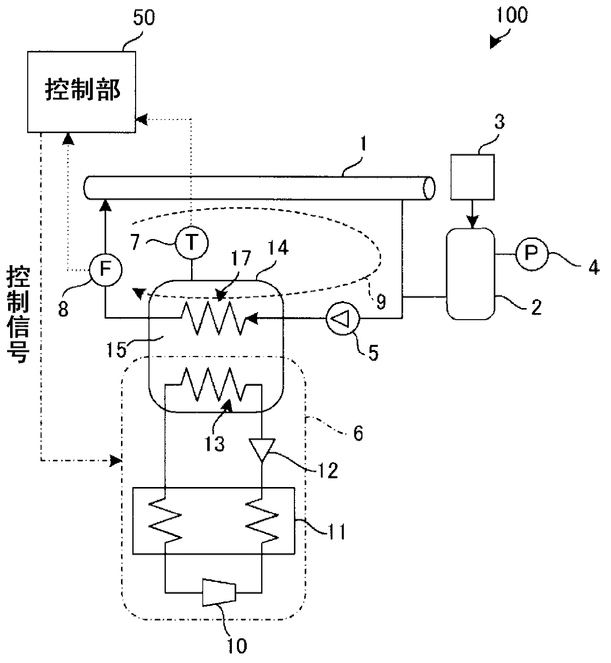
[0039] figure 1 It is a configuration diagram briefly explaining the overall configuration of the superconducting cable cooling system 100 according to the first embodiment. It should be noted that, for the reference Figure 10 DESCRIPTION OF THE BACKGROUND ART Common parts are assigned common symbols, and descriptions of details are appropriately omitted.

[0040] The cooling system 100 supplies the refrigerant used in the cooling process of the superconducting cable 1 to the heat exchange part 17 by the circulation pump 5 under pressure, cools it, and then supplies it to the superconducting cable 1 again, thereby forming a circulation path 9 and cooling the superconducting cable 1 . The conductive cable 1 is cooled. The superconducting cable 1 is formed of a high-temperature superconductor, and is cooled by a refrigerant (liquid nitrogen) flowing in the circulation path 9 . It should be noted that the refrigerant flowing in the circulation path 9 is figure 1 Although il...

no. 2 example

[0078] Figure 5 It is a configuration diagram schematically showing the overall configuration of a superconducting cable cooling system 100 according to the second embodiment. In addition, the same code|symbol is attached|subjected to the same structure as Example 1, and repeated description is abbreviate|omitted suitably.

[0079] The superconducting cable cooling system 100 according to the second embodiment is characterized in that a plurality of superconducting cables such as the superconducting cable 1 a and the superconducting cable 1 b can be cooled by one Brayton cycle refrigerator 6 . Circulation pumps 5a and 5b, heat exchange units 17a and 17b, flow sensors 8a and 8b, storage tanks 2a and 2b are respectively provided in each of superconducting cables 1a and 1b, and independent circulation paths 9a and 9b are formed. Since the circulation paths 9a and 9b are independent, they are configured to be able to control pressure, flow rate, etc. in a state of being set sepa...

no. 3 example

[0090] Next, refer to Figure 6 , the superconducting cable cooling system 100 according to the third embodiment will be described. Figure 6 It is a configuration diagram schematically showing the overall configuration of a superconducting cable cooling system 100 according to the third embodiment. It should be noted that the same symbols are assigned to the same structures as those in the above-mentioned first embodiment, and repeated descriptions are appropriately omitted.

[0091] In the case of superconducting cables used for long-distance power transmission, such as Figure 6 As shown, the superconducting cables 1a and 1b are often connected in series to achieve a longer distance. In such a case, since the pressurization capability of the circulation pump 5 has a limit, independent circulation paths 9 a and 9 b are provided corresponding to the respective superconducting cables.

[0092] exist Figure 6In the example shown, the adjacent superconducting cables 1a and ...


PUM


Abstract

The present invention pertains to a superconducting cable cooling system in which a coolant for cooling the superconducting cable (1) is pumped to a heat-exchanging section (17) by a circulation pump (5), and the superconducting cable is cooled by a refrigerating machine (6). Specifically, the superconducting cable cooling system is characterized by being equipped with a heat-exchanging unit (14) having a cooling space (15) filled with a liquid gas, a flow sensor (8) for detecting the flow rate of the coolant, a temperature sensor (7) for detecting the temperature of the liquid gas filled inside the heat-exchanging unit, and a control unit (50) for controlling the refrigerating machine on the basis of the values detected by the flow sensor and the temperature sensor such that the temperature of the liquid gas filled in the heat-exchanging unit is brought to a prescribed value.

Description

technical field [0001] The present invention relates to the technical field of a superconducting cable cooling system for cooling a superconducting cable used in electric power transmission and distribution to an extremely low temperature. Background technique [0002] A superconducting cable for power transmission and distribution made of a superconductor whose resistance value is approximately zero at extremely low temperatures. In order to ensure good power transmission efficiency of a superconducting cable, it is necessary to stably maintain the superconducting cable at an extremely low temperature, and research and development of a cooling system having such a cooling capacity is in progress. In general, a high-temperature superconductor is used as a material of a superconducting cable, and liquid nitrogen is used as a refrigerant for cooling. [0003] Here, refer to Figure 10 , the structure of a conventional superconducting cable cooling system 100 (hereinafter, app...

Claims


Application Information

Patent Timeline
Patent Type & Authority Applications(China)
IPC IPC(8): H01B12/16F25B9/00H02G9/00
CPCF25B9/14F25B2700/13F25B2700/21F25D3/10F25D16/00H01B12/16H02G15/34Y02E40/60F28F1/00
Inventor 山本惠一
Owner MAYEKAWA MFG CO LTD
Why Eureka
Try Eureka