

High temperature and high pressure sealing window used for constant volume combustion bomb
A technology of constant volume incendiary bombs, high temperature and high pressure, applied in the direction of engine sealing, engine components, mechanical equipment, etc., can solve problems such as poor sealing of fixed volume incendiary bomb windows, easy crushing of glass, sealing failure, etc., and easy to solve. The effect of crushing, disassembly and assembly is convenient, and the sealing performance is good.
- Summary
- Abstract
- Description
- Claims
- Application Information
AI Technical Summary
Problems solved by technology
Method used
Image

Examples
Embodiment Construction
[0027] The present invention will be described in further detail below through specific examples. The following examples can enable those skilled in the art to understand the present invention more comprehensively, but do not limit the present invention in any way.
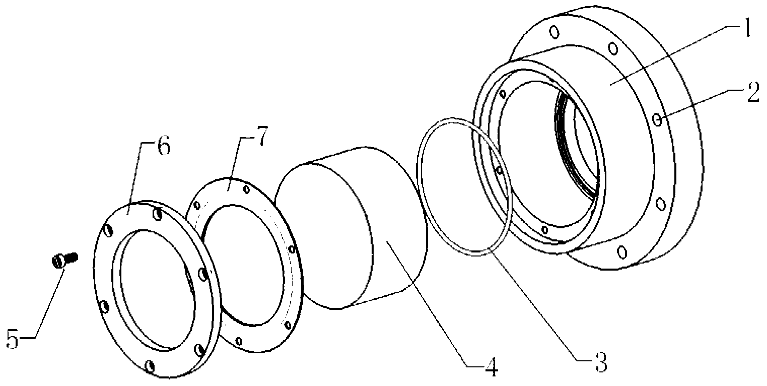
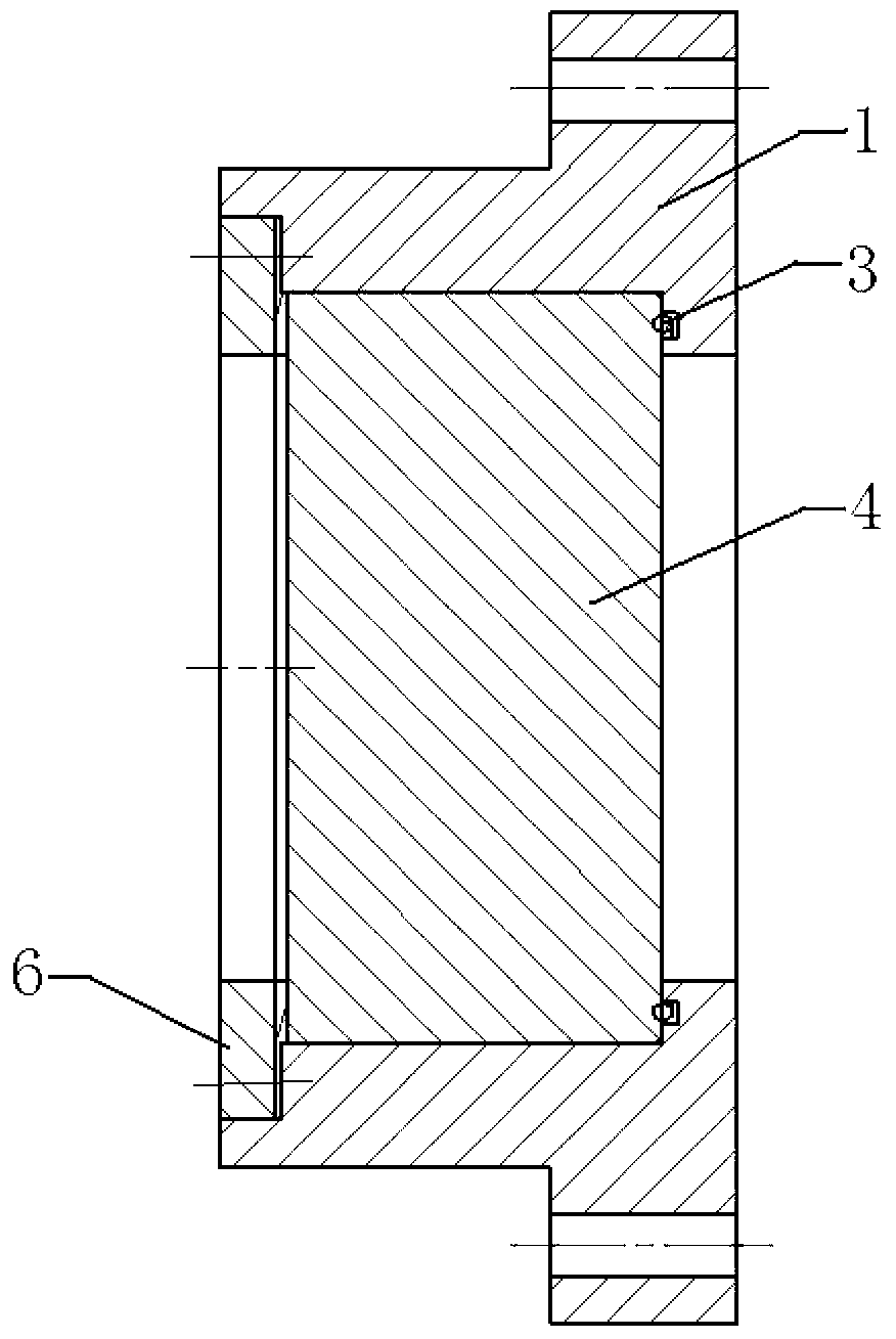
[0028] Such as figure 1 and figure 2 As shown, this embodiment discloses a high-temperature and high-pressure sealing window for constant-volume incendiary bombs, which mainly consists of a flange end cover 1, quartz glass 4, O-ring 3, retaining ring 6, high-strength graphite composite gasket 7 and Mounting bolts 5 components.
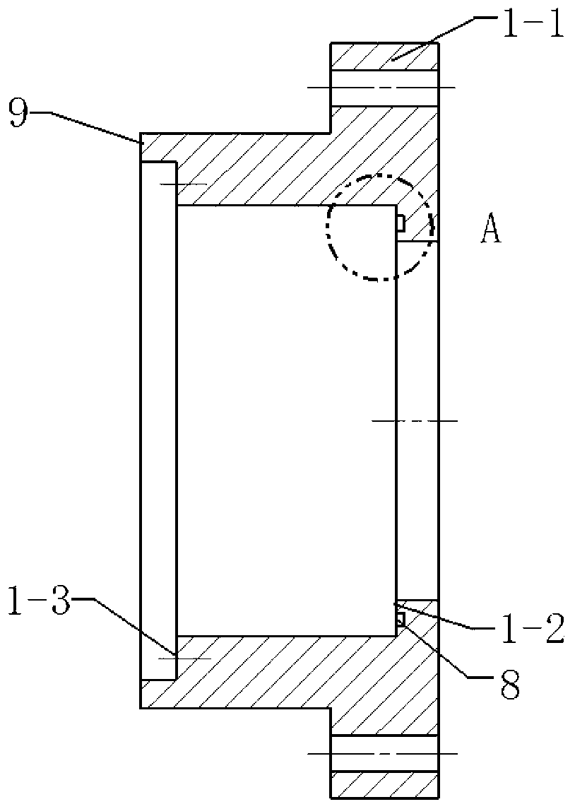
[0029] to combine image 3 As shown, the material of the flange end cover 1 is No. 45 steel, and its surface roughness is 3.2 μm, so as to meet certain machining accuracy requirements; the diameter of the visible window is 100 mm. An external boss 1-1 is arranged radially on the outer side of the flange end cover 1, and the outer boss 1-1 is provided with a mounting hole 2, and the fla...
PUM
| Property | Measurement | Unit |
|---|---|---|
| Surface roughness | aaaaa | aaaaa |
Abstract
Description
Claims
Application Information