
Method for testing fault modes of integrated switching current circuit

A failure mode and testing method technology, applied in the direction of electronic circuit testing, etc., can solve problems such as failure to achieve systematic and breakthrough development, mismatch error, imperfect conductance ratio, etc., to improve knowledge ability and generalization ability, The effect of reducing learning and training time and reducing test difficulty

Inactive Publication Date: 2013-08-28
CHANGSHA UNIVERSITY
View PDF3 Cites 14 Cited by
  • Summary
  • Abstract
  • Description
  • Claims
  • Application Information

AI Technical Summary

Problems solved by technology

[0003] However, due to the five non-ideal properties of the output-input conductance ratio error, mismatch error, charge injection error, adjustment error, and noise error caused by the imperfect MOS transistor operation in the switched current circuit, the test and The application is limited, the development is slow, and there has been no systematic and breakthrough development
[0004] Although the existing fault diagnosis method for switching current circuits based on fault dictionary (CN102129027A) overcomes the limitations of the traditional fault dictionary method, the diagnostic method based on a fault characteristic parameter, namely information entropy, has a higher fault pattern recognition rate and classification rate. Low, not suitable for testing and diagnosis of large-scale integrated switching current circuits with a large number of fault categories

Method used


Image

  • Method for testing fault modes of integrated switching current circuit
  • Method for testing fault modes of integrated switching current circuit
  • Method for testing fault modes of integrated switching current circuit

Examples


Embodiment 1

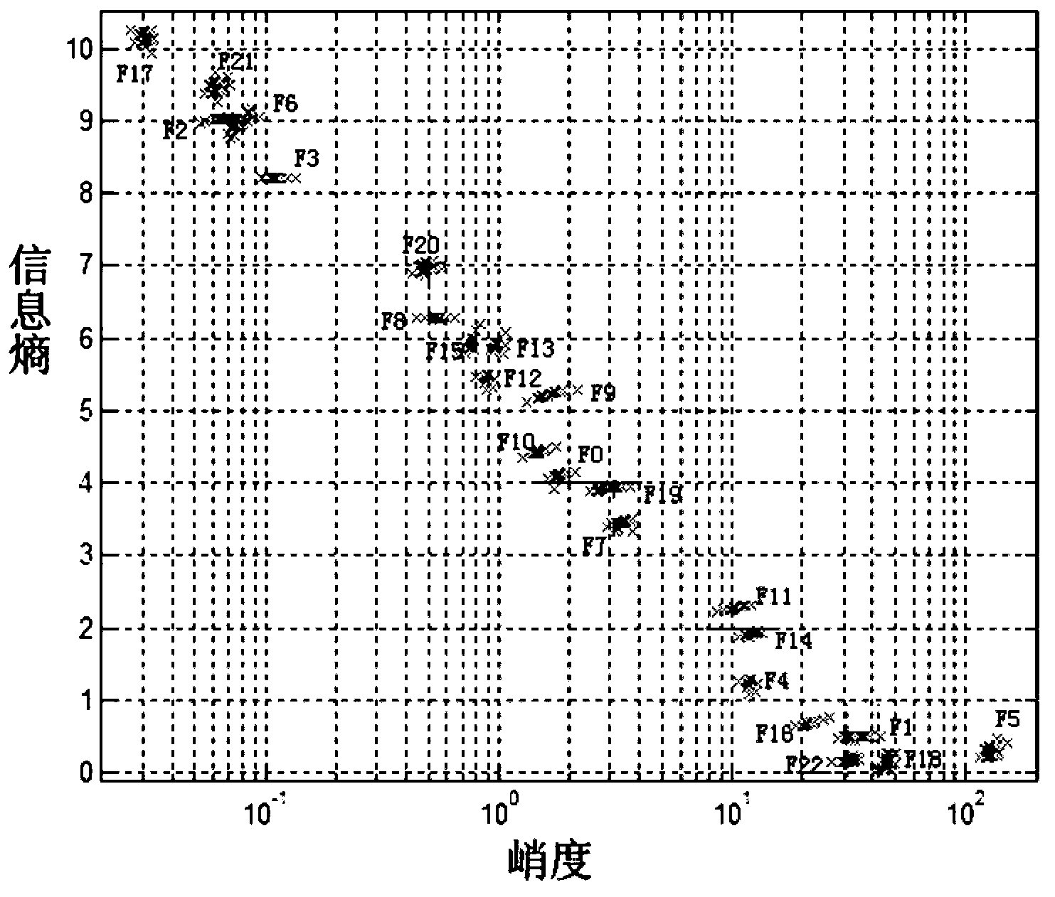
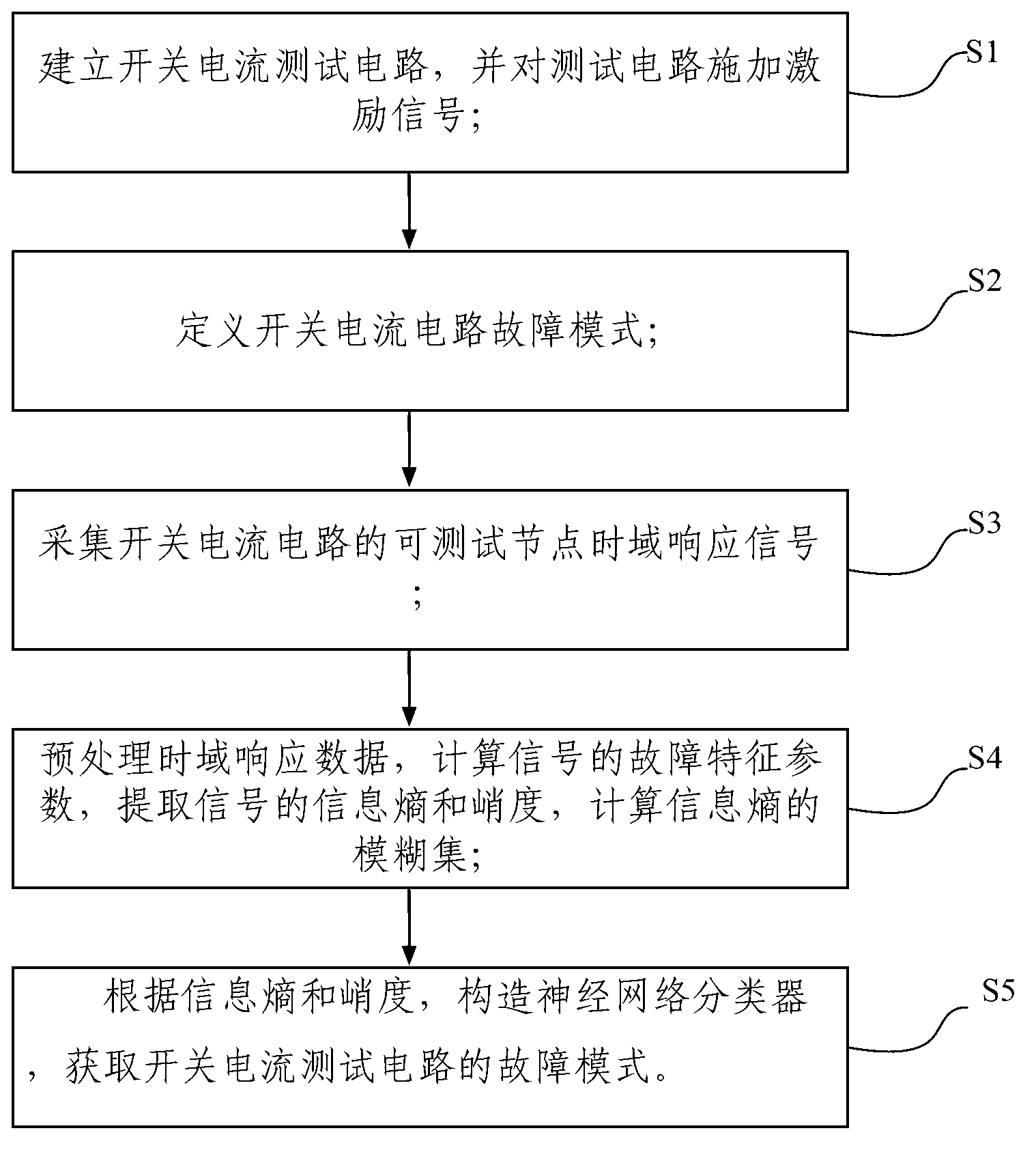
[0045] Such as figure 1 As shown, this embodiment records a failure mode test method for an integrated switching current circuit, comprising the following steps:

[0046] S1: Establish a switching current test circuit, and apply an excitation signal to the test circuit;

[0047] S2: Define the failure mode of the switching current circuit;

[0048] S3: collect the time-domain response signal of the testable node of the switching current circuit;

[0049] S4: Preprocess the time domain response data, calculate the fault characteristic parameters of the signal, extract the information entropy and kurtosis of the signal, and calculate the fuzzy set of information entropy;

[0050] S5: According to information entropy and kurtosis, construct a neural network classifier to obtain the failure mode of the switching current test circuit. The specific steps include:

[0051] S51: Construct a neural network training sample set, respectively construct soft fault and hard fault sample ...

Embodiment 2

[0060] This embodiment records a failure mode test method of an integrated switching current circuit, and its specific steps are as follows:

[0061] 1. Establish a representative test integrated switching current circuit and apply an excitation signal to the test circuit.

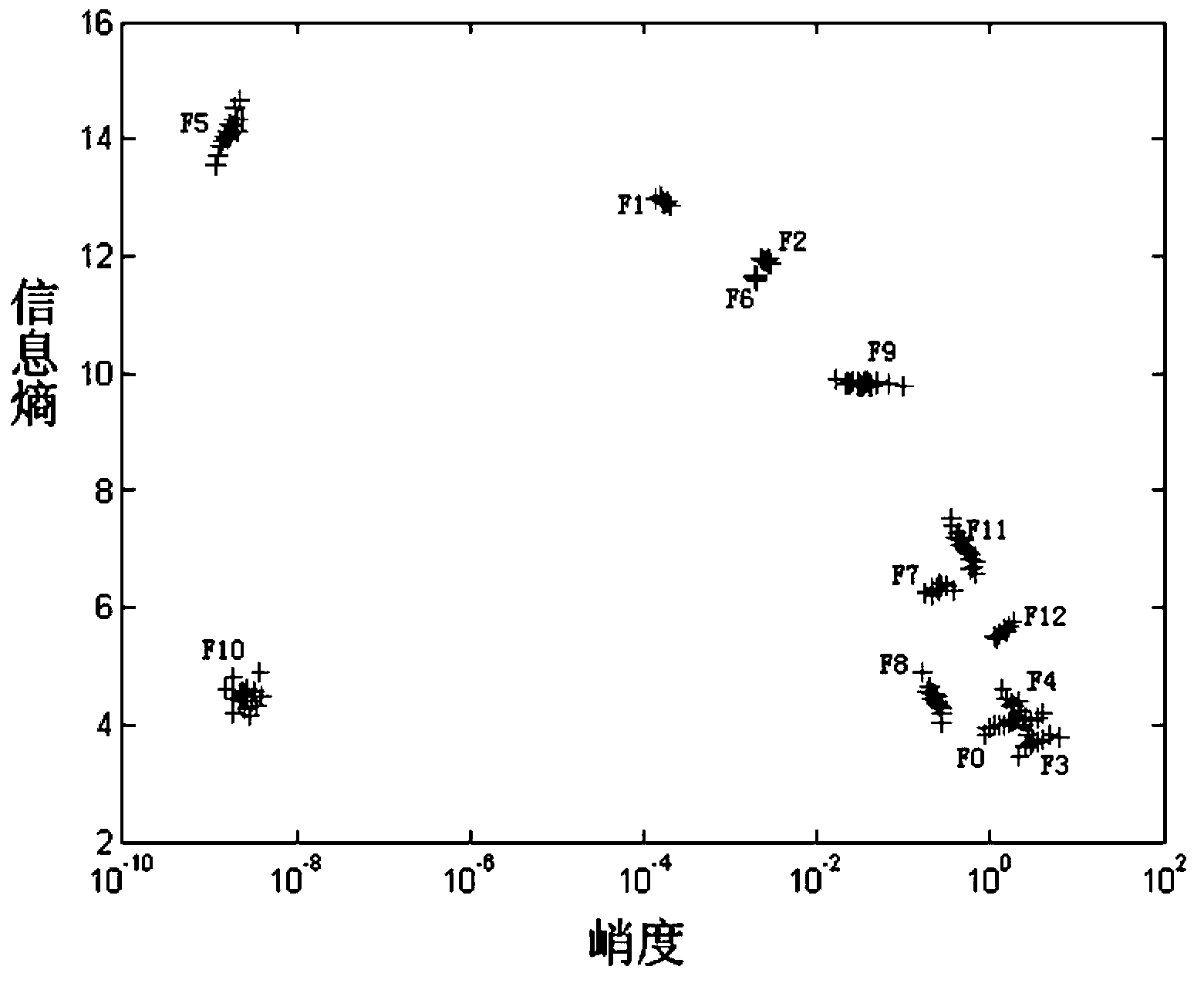
[0062] Such as figure 2 The test circuit of the sixth-order Chebyshev switching current low-pass filter is shown, and a sinusoidal signal with a frequency of 100KHZ is applied to it as the test excitation signal of the switching current circuit.

[0063] 2. Define the test circuit failure mode of the sixth-order Chebyshev switching current low-pass filter.

[0064] The failure mode of the sixth-order Chebyshev switched current low-pass filter includes a soft failure mode and a hard failure mode.

[0065] First define the soft fault mode, set the tolerance range of transconductance Gm to be 5% or 10% respectively, through sensitivity analysis, there are 11 transistors in the circuit where soft faults occ...


PUM


Abstract

The invention discloses a method for testing fault modes of an integrated switching current circuit. The method includes the following steps: S1, establishing a switching current test circuit, and applying an excitation signal to the test circuit, S2, defining the fault modes of the switching current circuit, S3, collecting testable node time-domain response signals of the switching current circuit, S4, preprocessing time-domain response data, calculating fault characteristic parameters of the signals, extracting information entropy and kurtosis of the signals, and calculating a fuzzy set of the information entropy, and S5, constructing a neural network classifier according to the information entropy and the kurtosis, and acquiring the fault modes of the switching current test circuit. The method for testing the fault modes of the integrated switching current circuit is suitable for tests on a large-scale and complicated integrated switching current circuit with a large number of fault categories and is high in accuracy rate of fault diagnosis.

Description

technical field [0001] The invention relates to the field of pattern recognition and current domain analog sampling data signal processing, in particular to a fault mode test method for an integrated switching current circuit. Background technique [0002] The switched current circuit is an analog sampling data system in the current domain. It has the advantages of no need for floating capacitors, compatible with digital VLSI technology, suitable for low-voltage operation, small chip area, and suitable for high-frequency applications. It is more and more popular in the field of mixed analog-digital system design are getting more and more attention. In the field of discrete-time analog circuits, switched current technology is increasingly considered to replace switched capacitor technology. [0003] However, due to the five non-ideal properties of the output-input conductance ratio error, mismatch error, charge injection error, adjustment error, and noise error caused by the...

Claims


Application Information

Patent Timeline
Patent Type & Authority Applications(China)
IPC IPC(8): G01R31/28
Inventor 龙英张镇何怡刚王江涛童耀南
Owner CHANGSHA UNIVERSITY
Learn More