
Centrifugal pendulum mechanism

A technology of centrifugal force pendulum and torque transmission device, which is applied in the direction of spring/shock absorber, vibration suppression adjustment, mechanical equipment, etc., and can solve the problem of large noise generation

Active Publication Date: 2013-08-28
SCHAEFFLER TECH AG & CO KG
View PDF5 Cites 40 Cited by
  • Summary
  • Abstract
  • Description
  • Claims
  • Application Information

AI Technical Summary

Problems solved by technology

By means of the curved configuration of the end faces of the pendulum masses, hooked pendulum masses are substantially excluded, but for this reason the noise generation is greater because the end sides of the pendulum masses facing each other are independent of the deflection of the pendulum masses. abut each other, i.e. collide with each other again under alternating operating conditions

Method used


Image

  • Centrifugal pendulum mechanism
  • Centrifugal pendulum mechanism
  • Centrifugal pendulum mechanism

Examples


Embodiment Construction

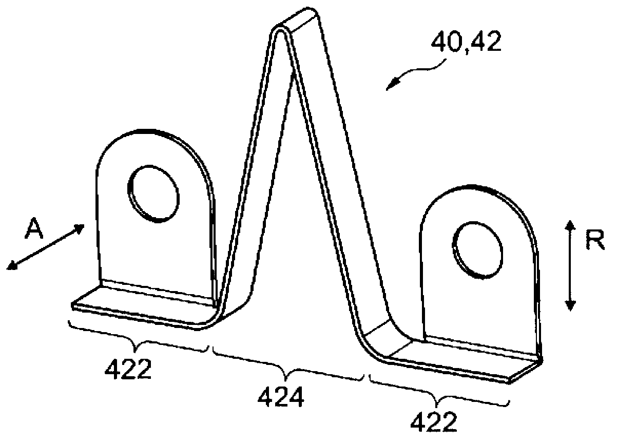
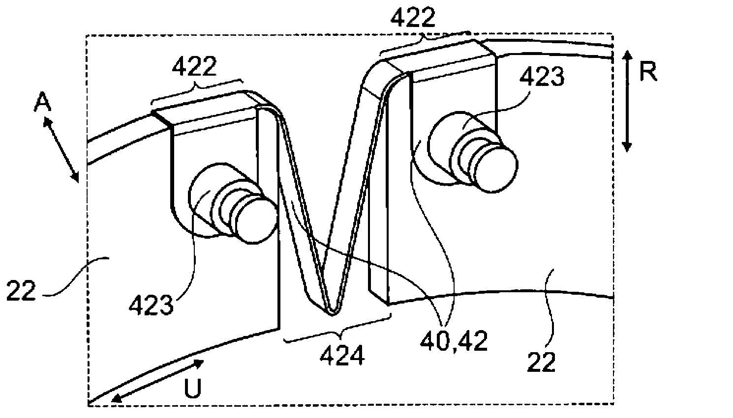
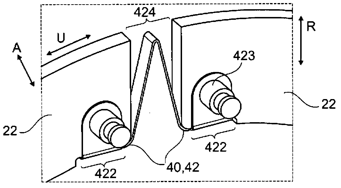
[0027] In a first embodiment of the first variant of the invention (see Figures 1 to 3 , and also Figures 7 to 10 ), the damping element 40 according to the invention for the centrifugal pendulum device 1 is configured as a spring element 42, the spring element 42 itself is designed as a leaf spring element 42 or a strip spring element 42, wherein the spring element 42 is configured at a certain The state or arrangement acts as a compression spring element 42 . In this case, the leaf spring element 42 is preferably made of a thin folded spring sheet, which is arranged on two directly adjacent Pendulum masses 22 or pairs of pendulum masses 20 are fastened there and in each case with fastening regions 422 . The spring region 424 of the leaf spring element 42 extends between two directly adjacent fastening regions 422 in the circumferential direction U, preferably only in certain states, namely in the pendulum mass 22 or the pendulum mass pair 20 With a defined relative posit...


PUM


Abstract

The invention relates to a centrifugal pendulum mechanism (1), in particular a trapezoidal centrifugal pendulum mechanism, for a damping device and / or a torque transmission device, in particular for a drive train of a motor vehicle, comprising a pendulum mass carrier (10), which can be rotated about a rotational axis (s) and on which a plurality of pendulum masses (22) or pendulum mass pairs (20) that can be moved relative to the pendulum mass carrier are provided in the circumferential direction (u), wherein two pendulum masses or pendulum mass pairs directly adjacent in the circumferential direction of the pendulum mass carrier are or can be mechanically coupled to each other by means of a damping element (40; 42; 44). The invention further relates to a damping device or a torque transmission device, in particular for a drive train of a motor vehicle; for example, a centrifugal pendulum, a torque converter, a clutch, a fluid coupling, a clutch assembly, a damper, a torsional vibration damper, a turbine damper, a pump damper, a dual mass converter, or a dual mass flywheel, or combinations thereof; wherein the damping device or the torque transmission device has a centrifugal pendulum mechanism according to the invention.

Description

technical field [0001] The invention relates to a centrifugal pendulum device, in particular a hanger-type centrifugal pendulum device, for a shock absorber device and / or a torque transmission device, in particular for a drive train of a motor vehicle. The invention also relates to a shock absorber device or a torque transfer device, in particular for use in a powertrain of a motor vehicle; A vibration damper, a turbine damper, a pump damper, a dual mass converter or a dual mass flywheel, or a combination thereof; wherein the damper arrangement or the torque transfer arrangement has a centrifugal pendulum arrangement according to the invention . Background technique [0002] On the shaft of a periodically operating machine, for example the crankshaft of an internal combustion engine of a motor vehicle, superimposed torsional vibrations occur during the rotational movement of the shaft, the frequency of which changes with the rotational speed of the shaft. Due to the combus...

Claims


Application Information

Patent Timeline
Patent Type & Authority Applications(China)
IPC IPC(8): F16F15/14
CPCF16F15/145Y10T74/2128F16F15/1214
Inventor P·莫夫拉扎达
Owner SCHAEFFLER TECH AG & CO KG
Learn More