Flow backing device of nuclear power centrifugation type excess heat discharge pump
A technology of waste heat discharge pump and return device, which is applied to the components of pumping device for elastic fluid, non-variable-capacity pump, pump, etc., can solve the water flow disorder at the impeller inlet, destroy the flow state, reduce the pump life, etc. problems, to achieve the effect of improving water flow turbulence, improving performance, and improving efficiency
- Summary
- Abstract
- Description
- Claims
- Application Information
AI Technical Summary
Problems solved by technology
Method used
Image
Examples
Embodiment 1
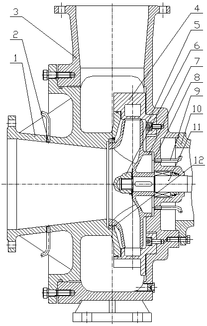
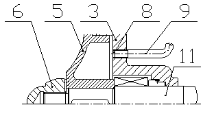
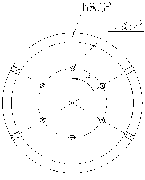
[0019] The waste heat discharge pump reflux device designed by the present invention, such as figure 1 As shown, on the front cover 1 and the pump body 3, five return holes 2 and 8 are evenly opened in the circumferential direction, respectively, and are fixedly connected with the two ends of the return pipeline 9, as shown in FIG. figure 2 shown. The area of the return hole is 6 times the area of the gap between the back ring 7 of the impeller and the pump body 3, the distance between the cross section of the pipe where the five return holes 2 are located is 0.8 times the diameter of the impeller inlet in the axial direction, and the diameter of the center line of the five return holes 8 Be 0.55 times the inner diameter of the impeller front mouth ring 12. The return holes 2 and 8 are arranged from the vertical center line, and at the same angle θ Circumferential rotation distribution, θ =72°. The liquid flow enters the rear pump cavity from the outlet of the impe...
Embodiment 2
[0021] On the front cover 1 and the pump body 3, eight return holes 2 and 8 are evenly opened in the circumferential direction, respectively, and are fixedly connected with the two ends of the return pipeline 9, such as figure 2 shown. The area of the return hole is 9 times the gap area between the impeller back ring 7 and the pump body 3, the distance between the section of the pipe where the 8 return holes 2 are located is 1.2 times the diameter of the impeller inlet in the axial direction, and the diameter of the center line of the 8 return holes 8 It is the inner diameter of 0.65 times of impeller front mouth ring 12. The return holes 2 and 8 are arranged from the vertical center line, and at the same angle θ Circumferential rotation distribution, θ =45°. The liquid flow enters the rear pump cavity from the outlet of the impeller 5, flows through the return hole 8 on the pump body, flows through the return line 9, reaches the return hole 2 of the front cover 1, and...
Embodiment 3
[0023] On the front cover 1 and the pump body 3, six return holes 2 and 8 are evenly opened in the circumferential direction, respectively, and are fixedly connected with the two ends of the return pipeline 9, such as figure 2 shown. The area of the return hole is 7 times of the gap area between the impeller back ring 7 and the pump body 3, the distance of the pipe section where the 6 return holes 2 are located is 1.0 times the diameter of the impeller inlet in the axial direction from the impeller inlet, and the diameter of the center line of the 6 return holes 8 It is the internal diameter of 0.6 times of impeller front mouth ring 12. The return holes 2 and 8 are arranged from the vertical center line, and at the same angle θ Circumferential rotation distribution, θ =60°, such as image 3 shown. The liquid flow enters the rear pump cavity from the outlet of the impeller 5, flows through the return hole 8 on the pump body, flows through the return line 9, reaches the ...
PUM
 Abstract
Description
Claims
Application Information
 - R&D
- Intellectual Property
- Life Sciences
- Materials
- Tech Scout
- Unparalleled Data Quality
- Higher Quality Content
- 60% Fewer Hallucinations
Browse by: Latest US Patents, China's latest patents, Technical Efficacy Thesaurus, Application Domain, Technology Topic, Popular Technical Reports.
© 2025 PatSnap. All rights reserved.Legal|Privacy policy|Modern Slavery Act Transparency Statement|Sitemap|About US| Contact US: help@patsnap.com


