Fast testing instrument of variable ratio and polarity of current transformer and testing method thereof
A technology of current transformer and test method, applied in the direction of measuring electrical variables, instruments, measuring electricity, etc., can solve the problems of injury to equipment and persons, burns of wiring busbars, and bulky test equipment, so as to improve work efficiency and save time. , measure the precise effect
- Summary
- Abstract
- Description
- Claims
- Application Information
AI Technical Summary
Problems solved by technology
Method used
Image
Examples
Embodiment 1
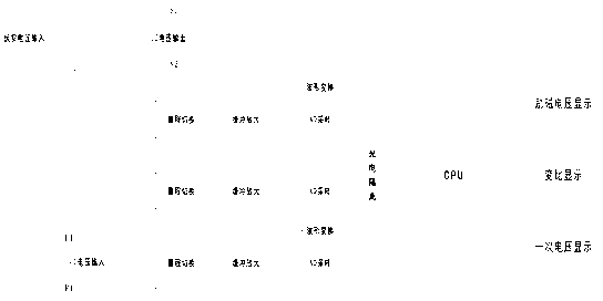
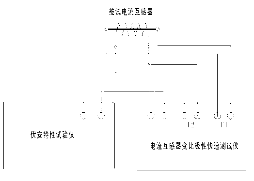
[0012] Embodiment 1: with reference to attached Figure 1-4 . A current transformer transformation ratio polarity rapid tester includes a current transformer transformation ratio tester. The current transformer transformation ratio tester belongs to the prior art and will not be described here. The signal output end of the current transformer ratio tester is connected one way to the signal input end of the excitation voltage display, one way to the signal input end of the transformation ratio display, and one way to the signal input end of the primary voltage display.
[0013] figure 1 Middle: 1. Excitation voltage U 2 Display window; 2. Volt-ampere voltage input terminal; 3. Ratio display window; 4. Excitation voltage U 2 Output terminal; 5. Secondary rated current selection current transformer; 6. Primary voltage U 1 Input terminal; 7. Primary voltage U 1 Display window; 8. Ground terminal; 9. Power input socket; 10. Power on; 11. Polarity indicator light; 12. Continuou...
Embodiment 2
[0015] Embodiment 2: On the basis of embodiment 1, a kind of testing method of current transformer transformation ratio polarity rapid tester, the voltage output by the volt-ampere tester is input to the volt-ampere voltage input end of this tester, by S 1 , S 2 Output excitation voltage U 2 To the secondary coil of the current transformer, the primary side of the current transformer is input to the primary voltage U of the tester 1 Input terminal, volt-ampere input to excitation voltage U 2 A small current transformer is connected in series at the output end to monitor the volt-ampere current I; U 2 , I, and U 1 Respectively through the corresponding range switching circuit, buffer amplifier circuit and AD sampling, and sent to the CPU through photoelectric isolation, the CPU measures the amplitude of the three signals, U 2 and U 1 It is also transformed into a square wave by the waveform conversion circuit, and sent to the CPU after photoelectric isolation for measuring...
PUM
 Abstract
Description
Claims
Application Information
 - R&D
- Intellectual Property
- Life Sciences
- Materials
- Tech Scout
- Unparalleled Data Quality
- Higher Quality Content
- 60% Fewer Hallucinations
Browse by: Latest US Patents, China's latest patents, Technical Efficacy Thesaurus, Application Domain, Technology Topic, Popular Technical Reports.
© 2025 PatSnap. All rights reserved.Legal|Privacy policy|Modern Slavery Act Transparency Statement|Sitemap|About US| Contact US: help@patsnap.com


