Electronic transformer amplitude and phase error checking system with networked detection function

An electronic transformer and phase error technology, applied in the direction of measuring electricity, measuring electrical variables, instruments, etc., can solve the problems that the performance of the whole circuit cannot be verified, cannot be tested, and merge unit port tests, etc., to avoid tedious work and The effect of testing blind spots, reducing equipment testing time, and simplifying the test system

Active Publication Date: 2013-09-04
STATE GRID CORP OF CHINA +2
View PDF9 Cites 47 Cited by
  • Summary
  • Abstract
  • Description
  • Claims
  • Application Information

AI Technical Summary

Problems solved by technology

[0007] When performing electronic transformer calibration, it is generally necessary to configure a merging unit device to cooperate with the function and accuracy test of the transformer. The actual operating merging unit, that is, the entire measurement circuit of the electronic transformer, cannot be tested, or cannot be tested for the upcoming The performance of the entire circuit on site cannot be verified, and there are obvious blind spots in the test; if the network-based test method is used, the application equipment and the overall measurement of the site can be performed without adding equipment. The circuit is fully tested, the integrity and reliability of the test

Method used


Image

  • Electronic transformer amplitude and phase error checking system with networked detection function
  • Electronic transformer amplitude and phase error checking system with networked detection function
  • Electronic transformer amplitude and phase error checking system with networked detection function

Examples


Embodiment Construction

[0026] The present invention will be described in detail below with reference to the accompanying drawings and specific embodiments.

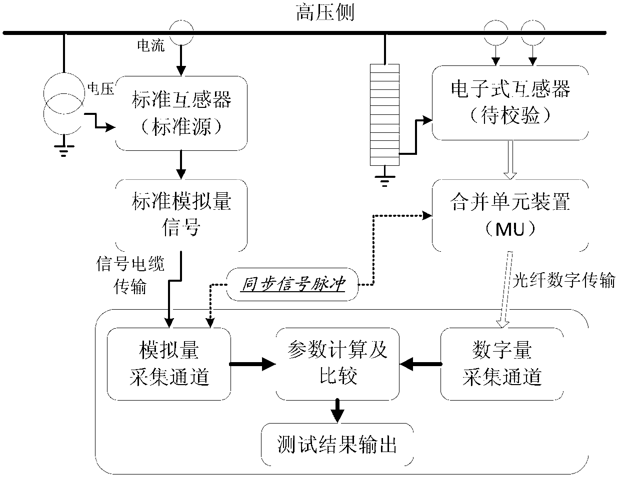
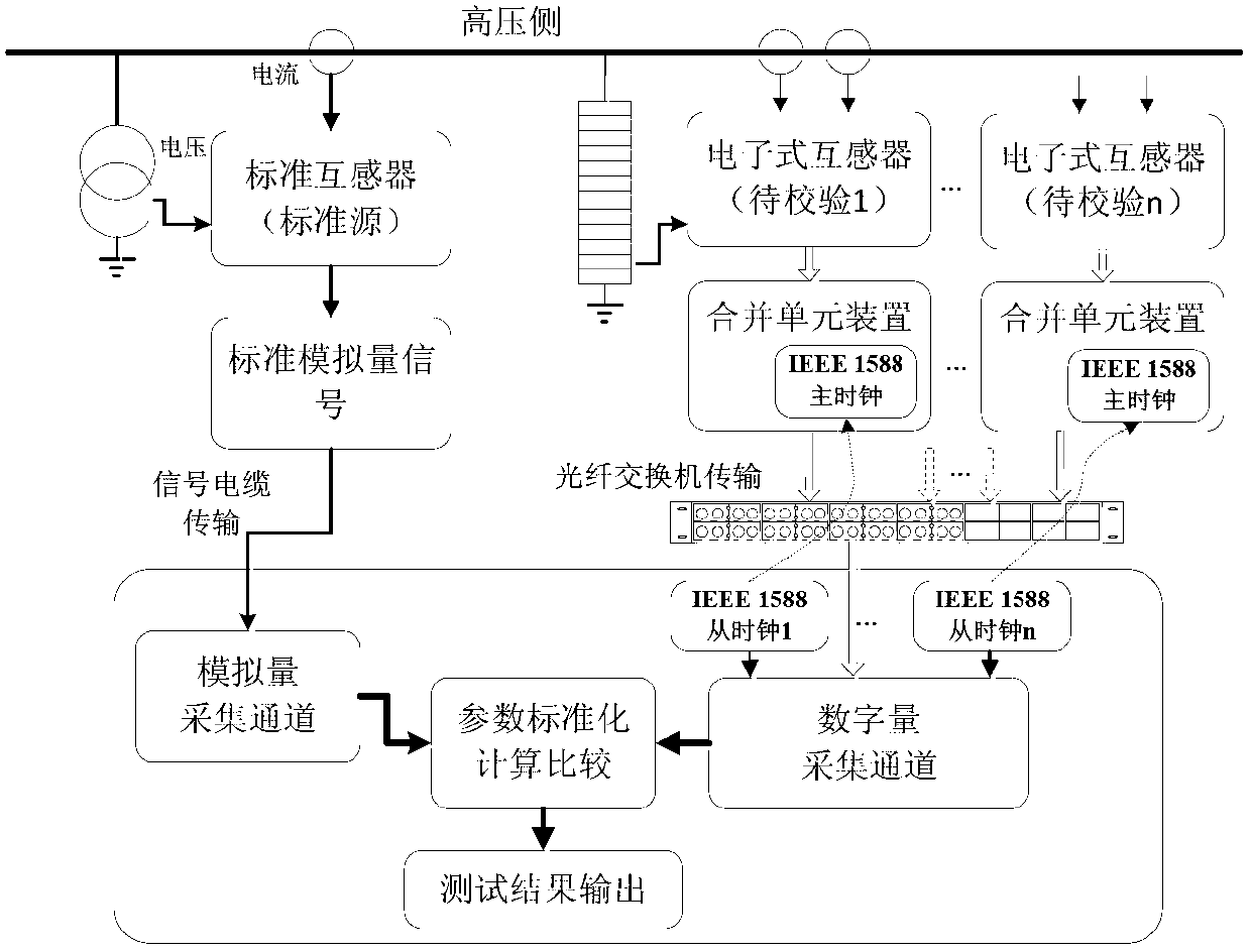
[0027] figure 2 It is a schematic diagram of the overall structure of the electronic transformer amplitude and phase error checking system that can be detected in a network of the present invention.

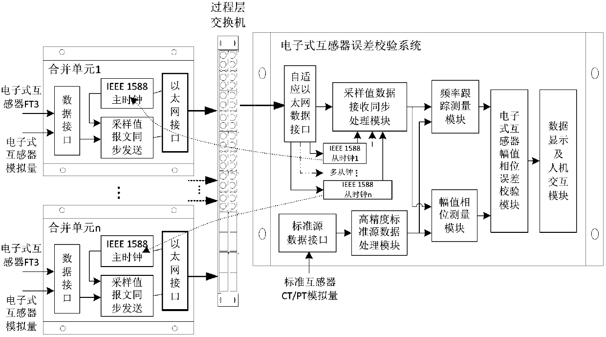
[0028] and figure 1In comparison, there have been obvious changes in the system structure. Firstly, the use of external synchronous signal pulses has been canceled, and a simplified IEEE 1588 master clock is implemented in each merging unit device. In the electronic transformer error checking system equipment Multiple slave clock functions are realized in the system, and the master clocks of each data source are independently tracked, which simplifies the structure of the test system and reduces the difficulty of testing the entire circuit of the on-site electronic transformer + merging unit. At the same time, through the process layer network ...


PUM


Abstract

The invention discloses an electronic transformer amplitude and phase error checking system with a networked detection function. Specifically, the system receives analog data acquired by a standard transformer, and digital sampling value message data sent by the electronic transformer, adopts a self-adaptive algorithm based on equal interval sampling at different sampling frequencies and signal quasi-synchronous characteristics, and obtains the amplitude, phase error and other parameters of each channel by standardized calculation through comparison. The system provided by the invention can be used for amplitude and phase error checking of electronic voltage and current transformers of various types in an intelligent substation, and can realize the networked detection of single-path or multi-path electronic transformers and merge unit circuits without external synchronization signal pulse in the traditional testing scheme, so that the transformer testing system is simplified, the impact of tedious discrete functional testing work and testing blind points of a multiplexer is avoided, the testing time of equipment is shortened, and the detection efficiency of the electronic transformer is improved.

Description

technical field [0001] The invention discloses an electronic transformer amplitude and phase error checking system capable of network detection, and belongs to the technical field of power system intelligent substations. Background technique [0002] With the rapid development of the power system, electromagnetic power transmission and transformation equipment has been fully developed. Voltage and current transformers are important equipment for providing voltage and current signals for power system energy measurement, relay protection equipment, measurement and control equipment, etc. The operation stability and reliability are closely related to the safe, reliable and economical operation of the power system. With the increase of the application environment and the increase of the voltage level, the traditional electromagnetic transformer gradually exposes the magnetic saturation, ferromagnetic resonance, high frequency Problems such as poor response characteristics, secon...

Claims


Application Information

Patent Timeline
IPC IPC(8): G01R35/02G01R31/00
Inventor 李澄陆玉军朱洁王宁陈颢王伏亮葛永高宁艳
Owner STATE GRID CORP OF CHINA
Why Eureka
Try Eureka