Magnetic-driven speaker

A loudspeaker and magnetic motion technology, applied in the field of loudspeakers, can solve the problems of reduced loudspeaker performance, excessive vibration diaphragm amplitude, decreased sensitivity, etc., and achieve the effects of saving precious metals, strong overload capacity, and good sound production efficiency

Inactive Publication Date: 2013-09-04
高魁民 +4
View PDF4 Cites 8 Cited by
  • Summary
  • Abstract
  • Description
  • Claims
  • Application Information

AI Technical Summary

Problems solved by technology

[0004] However, the indicators of the dynamic speaker are still not perfect, and its performance needs to be improved, such as:
[0005] (1) The magnetic flux density and uniformity of the magnetic gap where the voice coil is located needs to be improved. When the amplitude is large, the voice coil is easy to exceed the effective range of the inherent magnetic field, causing distortion
[0006] (2) During the use of the speaker, due to the temperature rise of the voice coil, the resistance of the voice coil increases and the sensitivity decreases, and as the heat continues to be generated, the temperature of the voice coil rises sharply. When it reaches the tolerance limit of the voice coil material , the adhesive is aging, the voice coil is loose or burned
[0007] (3) Low impedance, speakers for broadcasting and firefighting need to be equipped with line-to-line transformers, and the efficiency of the transformer is 80%, which seriously reduces the performance of the speakers
[0008] (4) The magnet itself radiates a magnetic field. If the speaker is placed together with household appliances such as TVs and computers, the magnet of the speaker will seriously interfere with the above-mentioned equipment, affect the effect of listening and watching, and will also destroy the magnetic field information of the magnetic card.
[0009] (5) The speaker will have a high peak on the frequency response curve near its lowest resonance frequency (fo), which is manifested as distortion caused by excessive vibration of the diaphragm

Method used


Image

  • Magnetic-driven speaker
  • Magnetic-driven speaker
  • Magnetic-driven speaker

Examples


Embodiment Construction

[0028] The present invention will be further described in detail below in conjunction with the drawings and specific embodiments. It should be understood that the specific embodiments described herein are only used to explain the present invention, but not to limit the present invention.

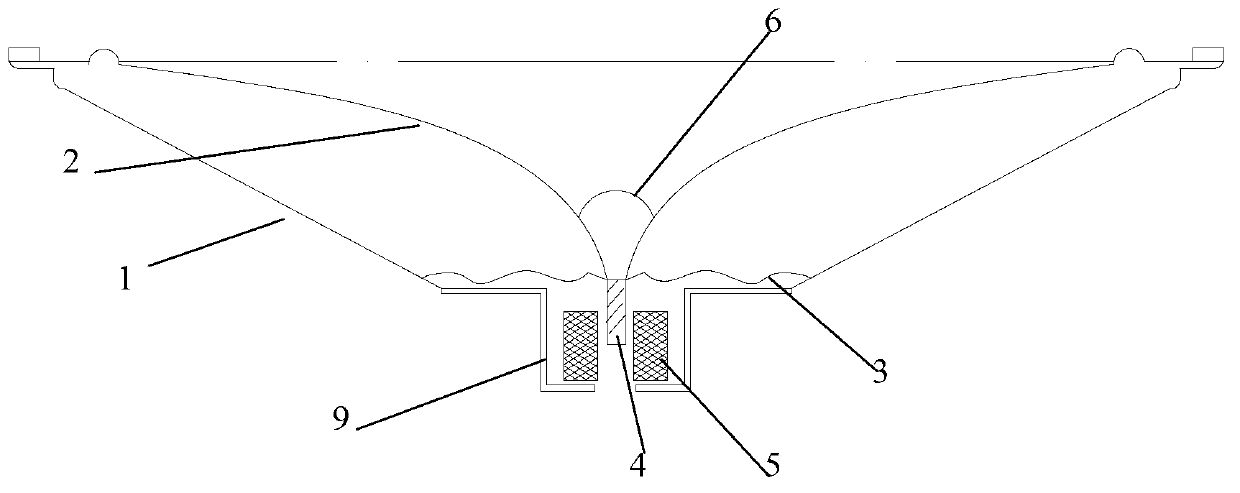
[0029] As shown in Figure 1, the magnetic loudspeaker of the first embodiment of the present invention includes a shielded shallow cone frame 1, a back cover diaphragm 2 fixedly connected to the top of the shielded shallow cone frame 1, a non-porous elastic wave 3, and a magnetic sound Column 4, and hollow fixed coil 5. Wherein, the bottom surface of the back cover diaphragm is fixedly connected to the center of the upper end surface of the non-porous elastic wave 3, the center of the lower end surface of the non-porous elastic wave is fixedly connected to the magnetic sound column 4, and the hollow fixed coil 5 is fixedly arranged in a shielded type. The shallow basin stand 1 is located below...


PUM


Abstract

The invention discloses a magnetic-driven speaker, comprising a basin stand, a bottom sealing vibrating diaphragm, an imporous damper, a magnetic column loudspeaker, hollow fixed coils and a shield isolation hood, wherein the periphery of the bottom sealing vibrating diaphragm is fixedly connected with the top end of the basin stand; the shield isolation hood is arranged at the bottom end of the basin stand; the bottom surface center of the bottom sealing vibrating diaphragm is fixedly connected with the surface of the upper end face of the imporous damper; the center of the lower end face of the imporous damper is fixedly connected with the magnetic column loudspeaker; and the hollow fixed coils are fixedly arranged in the shield isolation hood and are located under the magnetic column loudspeaker. By using the magnetic-driven speaker made according to the technical scheme of the invention, the magnetic-driven speaker has the characteristics that the sensitivity is high, the sounding efficiency is good, the overload capacity is strong, the frequency loss is low, the dynamic range is large, the frequency is wide, the produced product is light in the whole weight, a large amount of noble metal can be saved, the device size can be reduced, the failure rate of the device is reduced, the economy is good, and the telegraphy development can be driven.

Description

Technical field [0001] The present invention relates to the technical field of loudspeakers, in particular to a magnetic loudspeaker. Background technique [0002] Loudspeaker, also known as horn, is a kind of electrical energy conversion device. It is an electro-acoustic transducer that converts electrical signals into acoustic signals through a certain physical effect and radiates to the surrounding medium, realizing the physical effect of electro-acoustic energy conversion. No matter in the sound reproduction system or in the electric sound reinforcement system, it is the last link in the final restoration of electricity to sound, and it is the apple of the entire electric sound system. [0003] The dynamic speaker has experienced a long history of development. Over the years, its performance has been continuously improved and improved, and it has become the most extensive speaker at present. The existing dynamic speaker includes a vibration system and a magnetic circuit system....

Claims


Application Information

Patent Timeline
Patent Type & Authority Applications(China)
IPC IPC(8): H04R9/06H04R9/02
Inventor 高魁民高洋马群麟董丽英马莹
Owner 高魁民
Why Eureka
Try Eureka