
Powder conveyor

A powder conveying and conveying trough technology, which is applied in the direction of conveyors, conveying bulk materials, transportation and packaging, etc., can solve problems such as low production efficiency, large dust, and failure to meet actual requirements

Inactive Publication Date: 2013-09-11
SHANDONG YUANYOU HEAVY IND SCI & TECH
View PDF6 Cites 5 Cited by
  • Summary
  • Abstract
  • Description
  • Claims
  • Application Information

AI Technical Summary

Problems solved by technology

[0002] At present, in the production process of commercial concrete in my country, most of the powder used in the production process adopts the feeding system of screw machine to convey the powder. The system production process is simple, easy to operate, and strong in stability, but it has the following disadvantages: First, The feeding process is long and the production efficiency is low; the second is that the transmission power is large, and the energy waste is large; the third is that due to the exposure of the powder conveying device, the leakage of the powder can easily cause environmental pollution
Some also use air chute to feed, but use compressed air as power, which also has a large transmission power, and the gas contains oil and water, and enters the weighing hopper with the powder, resulting in large dust, which affects the powder conveying effect
In the case of increasingly stringent environmental protection requirements, this type of equipment has become less and less practical

Method used


Image

  • Powder conveyor
  • Powder conveyor
  • Powder conveyor

Examples


Embodiment Construction

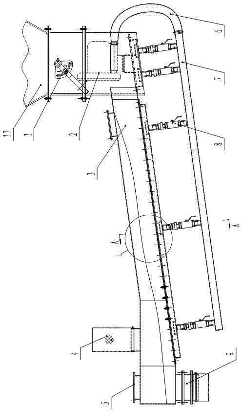
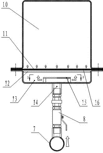
[0019] With reference to the accompanying drawings, the powder conveyor includes a powder bin 17, which is provided with a feed valve 1, the bottom of the powder bin 17 is connected with a delivery tank 3, and a discharge valve 9 is installed at the end of the delivery tank 3 to convey The trough 3 is inclined downward from the feed end to the discharge end, and its inclination angle is between 5-10°. In the conveying trough 3, there is a powder conveying bin 10 and The breathable interlayer of the lower air chamber 13, the breathable interlayer includes a support frame 12 supported on the inner wall of the delivery tank 3, and the support frame 12 is laid with a steel wire mesh 16, and the steel mesh 16 can also be replaced by other high-strength mesh materials , The steel wire mesh 16 is laid with a high-strength air-permeable cloth 11, and the high-strength air-permeable cloth 11 is a polyester air-permeable cloth. For the convenience of processing, the conveying trough 3 i...


PUM


Abstract

The invention discloses a powder conveyor which comprises a powder warehouse. The bottom of the powder warehouse is communicated with a conveying trough, a discharge valve is mounted at the tail of the conveying trough, the conveying trough is inclined downwards from a feed end to a discharge end, a breathable interlayer is arranged in the conveying trough, is close to the bottom wall of the conveying trough and is used for dividing an inner cavity of the conveying trough into an upper powder conveying warehouse and a lower air chamber, a plurality of air inlets are formed in the bottom wall of the conveying trough, a ventilating pipe communicated with an air supply device is arranged below the conveying trough, the air inlets are communicated with the ventilating pipe through air inlet pipes, an air inlet buffer device corresponding to the upper portion of each air inlet is arranged in the air chamber, and a breathable filter bag is arranged on the upper portion of the tail end of the conveying trough. The powder conveyor is simple in structure, low in failure rate, high in conveying efficiency and low in energy consumption.

Description

technical field [0001] The invention relates to a powder conveyor. Background technique [0002] At present, in the production process of commercial concrete in my country, most of the powder used in the production process adopts the feeding system of screw machine to convey the powder. The system production process is simple, easy to operate, and strong in stability, but it has the following disadvantages: First, The feeding process is long and the production efficiency is low; the second is that the transmission power is large and the energy waste is large; the third is that due to the exposure of the powder conveying device, the leakage of the powder can easily cause environmental pollution. Some also use air chute to feed, but use compressed air as the power, which also has high transmission power, and the gas contains oil and water, and enters the weighing hopper with the powder, resulting in large dust and affecting the powder conveying effect. In the case of increasin...

Claims


Application Information

Patent Timeline
IPC IPC(8): B65G53/02
Inventor 杨志仿魏宏旭崔明德于新波孙立伟
Owner SHANDONG YUANYOU HEAVY IND SCI & TECH
Learn More